Main Functions Si18-201
84 Main Functions
1.1.6 Fan Speed Control for Indoor Units
For FTK(X)25/35J,
FTK(X)50/60 H
Series
Control Mode
The airflow rate can be automatically controlled depending on the difference between the set
temperature and the room temperature. This is done through phase control and Hall IC control.
For more information about Hall IC, refer to ‘Hall IC check (A6)’ on page 309.
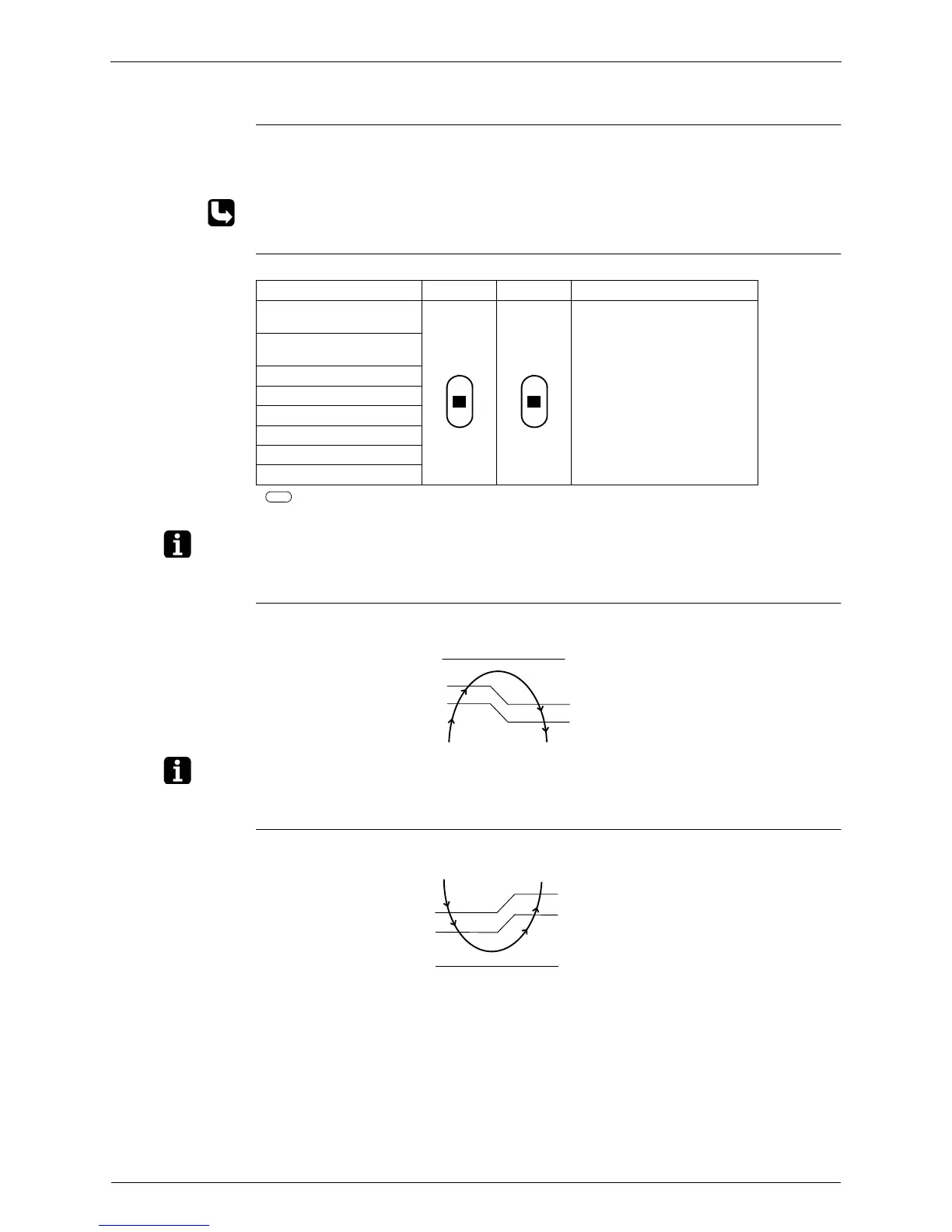
Phase Steps Phase control and fan speed control contains 8 steps: LLL, LL, L, ML, M, HM, H and HH.
= Within this range the airflow rate is automatically controlled when the AIRFLOW
ADJUSTING button is set to AUTOMATIC
Note: 1. During powerful operation, fan operate H tap + 50 - 70 rpm.
2. Fan stops during defrost operation.
Automatic Air
Flow Control for
Heating
The following drawing explains the principle for fan speed control for heating:
Note: When there is no operation and the night set mode turns on, the step is low. Refer to “Night set
mode” on page 89.
Automatic Air
Flow Control for
Cooling
The following drawing explains the principle of fan speed control for cooling:
Step Cooling Heating Dry mode
LLL (Heating thermostat
OFF)
H type : 500 - 860 rpm
(During powerful operation :
850 - 910 rpm)
J type : 800 - 980 rpm
(During powerful operation :
1050 rpm)
LL (Cooling thermostat
OFF)
L
ML
M
MH
H
HH (Powerful)
(RL010) (RL010)
-1.5˚C
-0.5˚C
-1˚C
-2˚C
L
ML
M
Thermostat
setting
temperature
Phase control
Temperature difference between
ambient and set temperature
fan speed
(RL012)
+1.5˚C
+0.5˚C
+2˚C
+1˚C
M
ML
L
fan speed
Temperature difference between
ambient and set temperature
Phase control
Thermostat
setting
temperature
(RL013)