6 x Parameter settings
Daikin RoCon HP
Daikin Controller
008.1420844_13 – 02/2016
Operating instructions
43
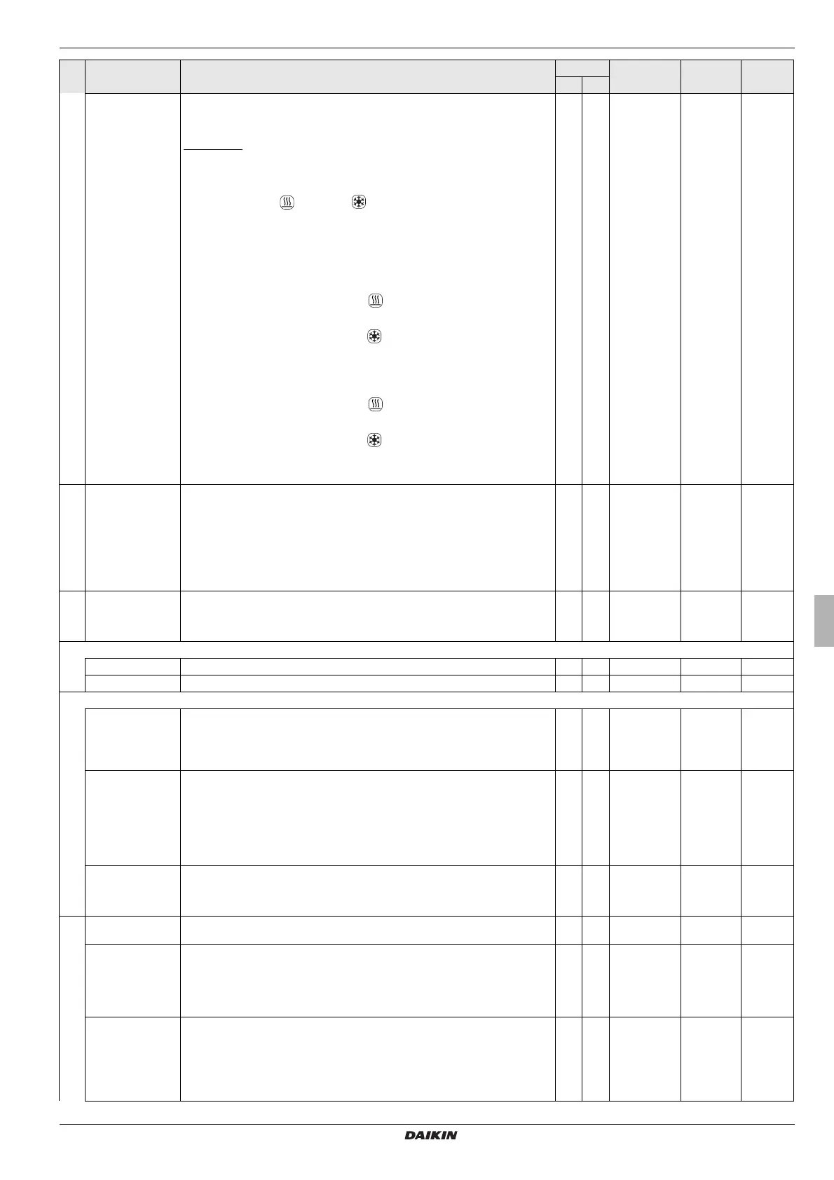
Interlink fct Configuration for systems operating with 2 different inflow target temperatures
(see section 3.6.6).
A possible use for this might be the additional integration of a FWXV(15/20)AVEB in a
surface heat
ing and cooling system.
Requirement: 2 room thermostats need to be connected to plug connection J16 on the
Daikin Altherma EHS(X/H).
– Off: Deactivated
– On: Evaluation of and cooling switching contacts at plug connection J16
on the RoCon BM1 circuit board.
Activation of cooling mode only possible by changing operating mode to "Cooling"
(see sect
ion 3.4.2).
Setting for the parameter [Room thermostat] no longer evaluated.
a) Open switching contacts: only fro
st protection active.
b) Operating modes "Heating" and "Automatic
1" / "Automatic 2" active during
switching cycles in day mode.
– Closed switching contact heating
= IL1:
→ The syst
em operates according to the normal infeed target temperature
according to the parameter settings in "HC Configuration" > "Heating".
– Closed switching contact cooling
= IL2:
→ The syst
em operates according to the increased inflow target temperature
(normal inflow target temperature + value of parameter [T-Flow CH adj].
Priority if both switching contacts are closed.
c) "Cooling" operating mode active.
– Closed switching contact heating
= IL1:
→ The syst
em operates according to the normal infeed target temperature
according to the parameter settings in "HC Configuration" > "Cooling".
– Closed switching contact cooling
= IL2:
→ The syst
em operates according to the reduced inflow target temperature
(normal inflow target temperature - value of parameter [T-Flow Cooling adj].
Priority if both switching contacts are closed.
N E Off
On
Off -
MF 1 Config Configuring the multi-function output (230 V, connection J14):
0: The output has no function.
1: Gathering pump – the output becomes active as soon as a heating circuit of the sys-
tem indicates a heat demand to the heat generator.
2: Circulation pump – the output is activated in accordance with the timer programme
of
the circulation pump or in accordance with the timer programme of the hot water
generation, depending on the parametrisation (see chapter 3.4.7).
3: Delivery pump – the output is active as soon
as there is a heat demand for the direct
heating circuit of the heat generator.
N E 0 - 3 2 1
Air Purge Activation of automatic bleeding of the Daikin Altherma EHS(X/H) and the connected
he
ating circuit (see section 3.6.10).
Off: Deactivated
On: Start of Air Purge
N E Off
On
Off -
PWM Config
Max Perform Pump Upper limit for modulation of the pump output N E 20 - 100 % 100 % 1 %
Min Perform Pump Lower limit for modulation of the pump output N E 10 - 100 % 50% 1 %
Sensor Config
Outside Config Configuration of the optional external temperature sensor RoCon OT1:
Off: No sensor evaluation
On: Sensor evaluation activated. This sensor
is evaluated for determination of the set
flow temperatures (see chapter 3.6.4) and displayed in the standard display). An error
message is generated if an outdoor t
emperature sensor is connected.
N E Off
On
Off -
Storage Config Configuration of water heating:
Inactive: No function for hot water generation.
Sensor: Function for hot water generation is act
ivated. A circulating tank temperature
sensor is evaluated for hot water generation (if no circulating tank temperature sensor
is connected, a fault message is generated).
Thermostat: Function for hot water generation is activated. A thermostatic switch (On
/
Off) is evaluated for hot water generation, and where "open brackets" are evaluated
as "no demand".
N E Inactive
Sensor
thermostat
Sensor -
Pressure Config Configuring the sensor for assessment of the system water pressure:
Off: No sensor evaluation
On: Sensor evaluation activated (if no pressure sensor
is connected, a fault message
is generated.)
N E Off
On
On -
Outside Temp Adap Individual adapting for the measured value of the outdoor temperature relevant for the
Con
troller.
N E -5.0 to +5.0 kW 0,0 K 0.1 K
Terminaladress Setting the terminal ID of the control unit for system access. The set value must be ap-
plicable for the entire system. Confirmation of
this parameter using the rotary switch
reinitialises the controller.
All settings, except "Off", empower the user of the control unit to activate the terminal
f
unction and thus to operate all RoCon system components with a valid device ID
(see chapter 3.4.9 and 4.1).
N E Off, 0 - 9 Off 1
System Config System configuration of the unit, consisting of
the sensor configuration and data bus
configuration. If you answer "yes" to the enquiry about using the standard configuration
when starting the unit for the first time, the basic configuration for the installed heat
generator will be activated automatically.
Confirmation of this parameter setting as "i
nactive" or "delete" using the rotary switch
reinitialises the controller. A fault message follows. After this the rotary switch must be
set to the position "Info". Use the rotary switch to select the required menu item.
N E Inactive
Active
Delete
Active.
-
Sub-
level
Parameter Description Access Setting range
Min / Max
Factory
setting
Increment
BE HF
 Loading...