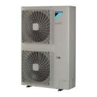
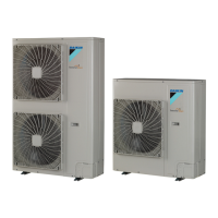
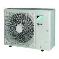
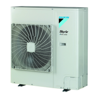
General Outline: Outdoor Units ESIE02–01
1–24 Part 1 – System Outline
3
1
1
4
5
1.12 RP200B7W1, RP250B7W1, RYP200B7W1 and RYP250B7W1:
Installation and Service Space
Wall height The illustration below shows the wall height limits (mm).
Single installation The illustration below shows the required installation and service space (mm).
Installation in row The illustration below shows the required installation and service space (mm).
FS
h2
h1500
1500
In case 1 or 2:
If... Then...
Frontal wall height >
1500 mm
Add h2/2 to the values
mentioned in this section.
Suction wall height >
500 mm
Add h1/2 to the values
mentioned in this section.
Front side
Suction side
≥ 50 ≥ 50
≥ 500
≥ 100
≥ 10 ≥ 10
≥ 500
≥ 300
≥ 10
≥ 300
F
S
S
F
S
F
Case 1 Case 2 Case 3
≥
10
≥
500
≥
10
≥
300
≥
20
≥
20
≥
50
≥
500
≥
50
≥
100
≥
100
≥
100
≥
200
≥
300
≥
400
≥
400
S
F
S
F
S
F
Case 1
Case 2
Case 3

 Loading...
