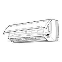
ESIE02–01 Overview of the cooling mode functions
Part 2 – Functional Description 2–27
3
2
4
5
1
2.3 Freeze-Up Function in Cooling or Dry Keep
Applicable units ■ R(Y)P71-250B
■ FHYCP, FHYBP, FDYP, FUYP, FAYP and FHYKP
Starting conditions In order to avoid formation of ice on the indoor heat exchanger in cooling and dry mode, the system
automatically starts up a freeze-up cycle when a number of specific conditions are fulfilled.
Starting conditions 1
■ The compressor has been running for less than A min.
■ The integral cooling capacity decreases for 200 s continuously (see integral capacity calculation
further in this section).
■ Te < -1˚C for 1 min continuously (0˚C for FAY indoor units).
Starting conditions 2 (FAYP indoor units)
■ The compressor has been running for more than A min.
■ The integral cooling capacity decreases for B s continuously and Te < F˚C for 1 min continuously
(see integral capacity calculation further in this section), or
Te < -1˚C for 1 min continuously.
Starting conditions 2 (not-FAYP indoor units)
■ The compressor has been running for more than A min.
■ The integral cooling capacity decreases for B s continuously (see integral capacity calculation
further in this section).
■ Te < C˚C for 1 min continuously.
Starting condition 3
■ Te < D˚C for E min accumulated.
Starting conditions 4
■ The compressor has been running for more than 1 min continuously while Te ≤ -5˚C.
■ Compressor ON → OFF.
Starting conditions 5
■ The compressor has been running for more than 8 min continuously while
the outdoor ambient temp. < -2.9 x room temp. + 79˚C.
■ The compressor has been running for more than 8 min continuously while Te < -5˚C for 1 min
continuously.
A, B, C, D, E and F The table below contains the values of A, B, C, D, E and F in function of the DIP switch settings on the
outdoor PCB.
Mode
DIP switch
ABCDEF
2-3 2-4
0 OFF OFF 20 min 100 s -1˚C -1˚C 25 min 0˚C
1ON
2 OFF ON 8 min 0 s 0˚C +1˚C 15 min
3ON 5 min +2˚C +3˚C +2˚C

 Loading...
