ESIE02–01 Functional Diagrams
Part 1 – System Outline 1–77
3
1
4
5
4.7 RP71B7V1, RP71B7W1, RP71B7T1, RP100B7V1, RP100B7W1,
RP100B7T1, RP125B7W1 and RP125B7T1
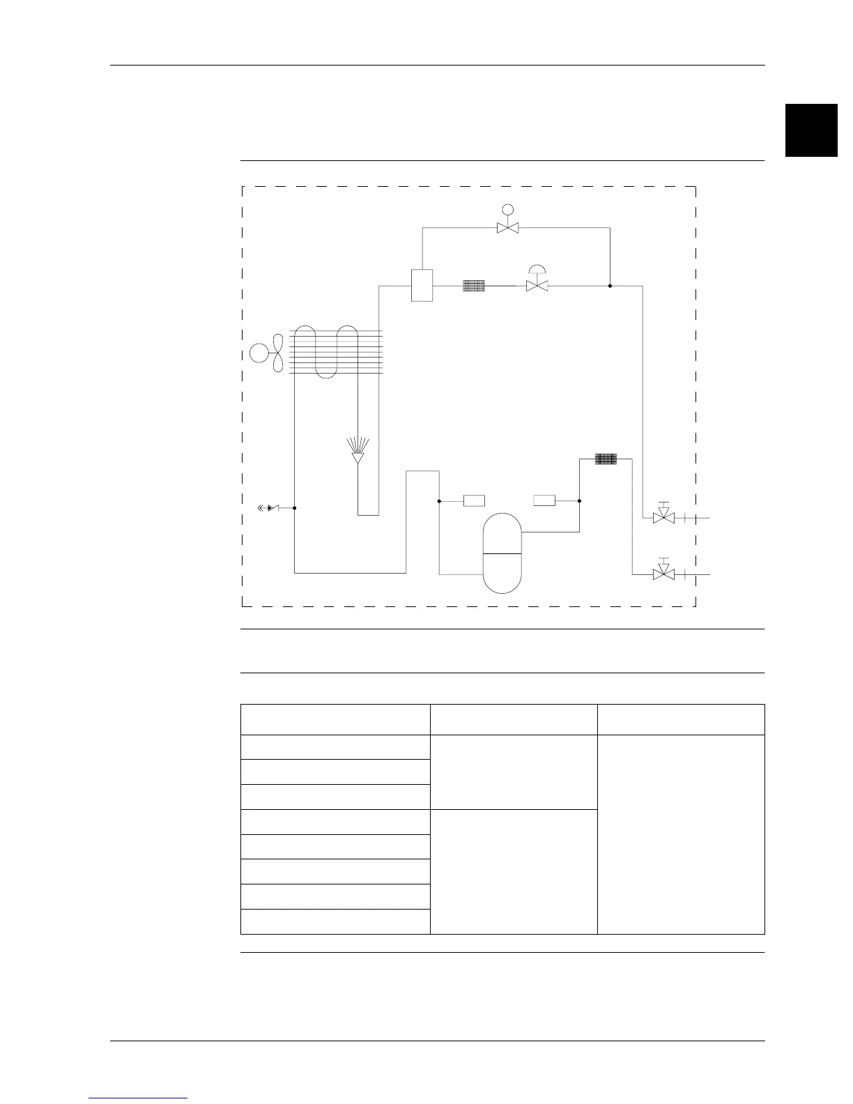
Functional diagram The illustration below shows the functional diagram of the refrigeration circuit.
Components For a description of the components, see ’Piping Components’ on page 1–93.
Pipe connection
diameters
The table below contains the refrigerant pipe connection diameters.
p <
p >
SV
19
11
4
2b
68
10
7
13 12
3
Liquid
piping
Gas
piping
14
8
Model ∅ Gas pipe (flare) ∅ Liquid pipe (flare)
RP71B7V1 15.87 mm 9.52 mm
RP71B7W1
RP71B7T1
RP100B7V1 19.05 mm
RP100B7W1
RP100B7T1
RP125B7W1
RP125B7T1

 Loading...


