18 Spyder 3 CL User's Manual
03-032-20008-00 DALSA
!
!
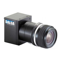
Figure 8: Spyder 3 CL Input and Output Connectors
WARNING: It is extremely important that you apply the appropriate voltages to your
camera. Incorrect voltages may damage the camera. See section 2.4 for more details.
2.3 Power Connector
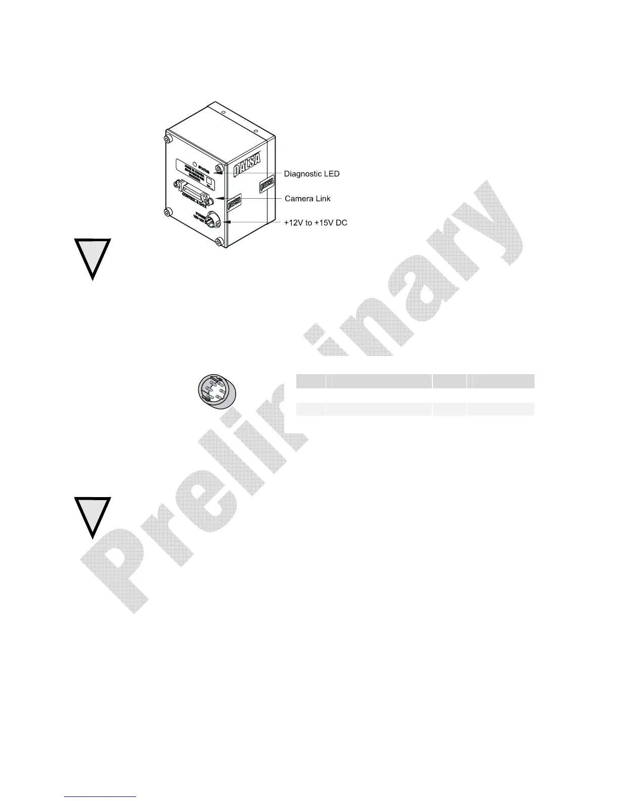
Figure 9: Hirose 6-pin Circular Male—Power Connector
Hirose 6-pin Circular Male
5
4
6
2
3
1
Mating Part: HIROSE
HR10A-7P-6S
The camera requires a single voltage input (+12 to +15V). The camera meets all
performance specifications using standard switching power supplies, although well-
regulated linear supplies provide optimum performance.
WARNING: When setting up the camera’s power supplies follow these guidelines:
• Apply the appropriate voltages
• Protect the camera with a
fast-blow fuse between power supply and camera.
• Do not use the shield on a multi-conductor cable for ground.
• Keep leads as short as possible to reduce voltage drop.
• Use high-quality
linear supplies to minimize noise.
Note: Camera performance specifications are not guaranteed if your power supply does not meet
these requirements.
DALSA offers a power supply with attached 6’ power cable that meets the Spyder 3 CL
camera’s requirements, but it should not be considered the only choice. Many high
quality supplies are available from other vendors. Visit the www.dalsa.com/mv Web site
for a list of companies that make power supplies that meet the camera’s requirements.
The companies listed should not be considered the only choices.
Table 3: Hirose Pin Description
Pin Description Pin Description
1 Min +12 to Max +15V 4 GND
2 Min +12 to Max +15V 5 GND
3 Min +12 to Max +15V 6 GND

 Loading...