Spyder 3 CL User's Manual 29
DALSA 03-032-20008-00
3.3 Camera Output Format
How to Configure Camera Output
Using the camera link mode and pixel readout direction commands
Use the camera link mode (clm) command to determine the camera’s Camera Link
configuration, the number of output taps, and the bit depth. Use the pixel readout
direction (
smm) command to select the camera’s pixel readout direction.
The following tables summarize the possible camera configurations for each of the S3-xx
camera models.
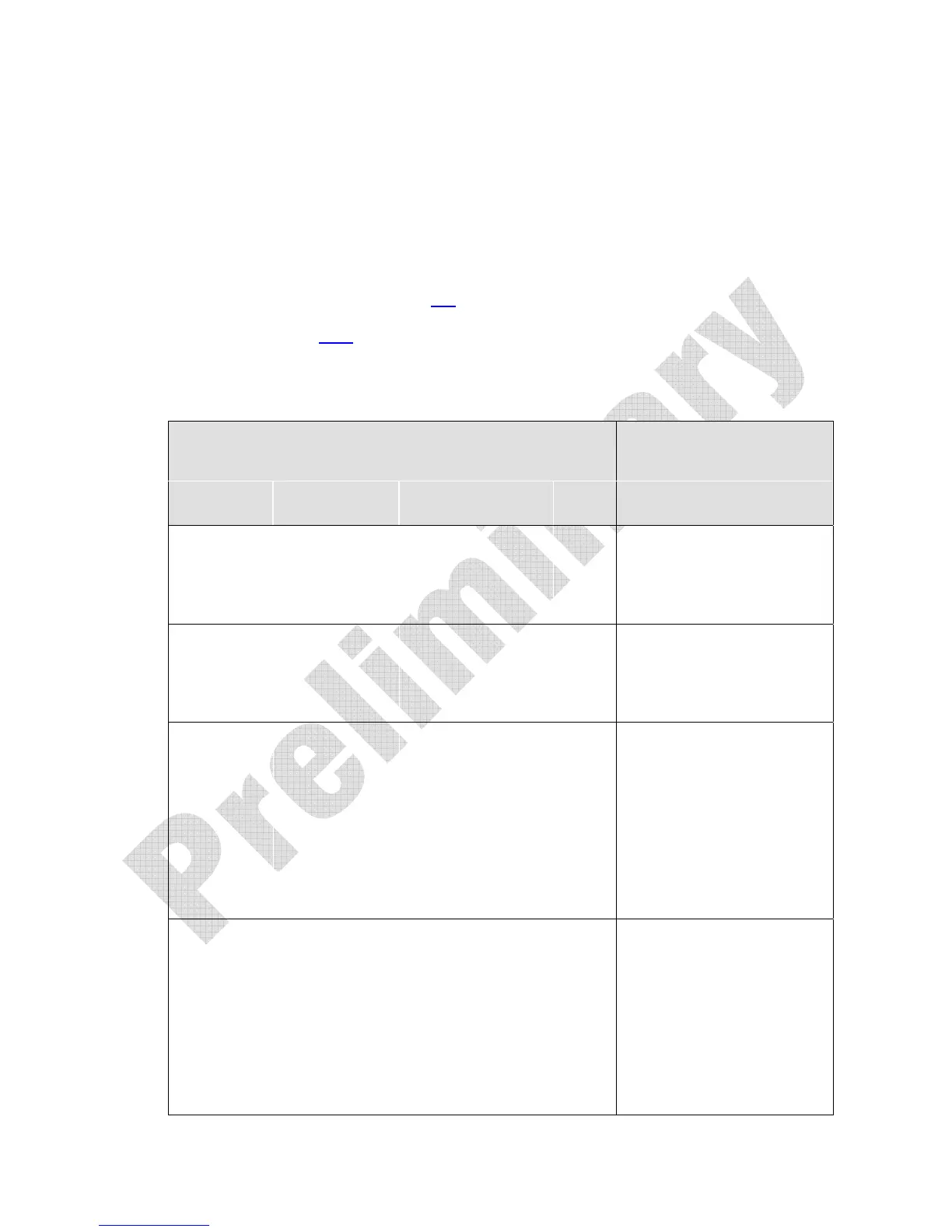
Table 9: S3-X0-01K40 Data Readout Configurations
Camera Link Mode Configuration (Controlled by clm
command)
Readout Direction
(Controlled by smm
command)
Command Models CCD and Camera
Link Taps
Bit
Depth
smm 0 increment =1
smm 1 increment = -1
clm 0
S3-10-01K40 1 Camera Link taps
8 smm 0 = CL tap 1 (1-1024)
smm 1 = CL tap 1 (1024-1)
S3-10-02K40 smm 0 = CL tap 1 (1-2048)
smm 1 = CL tap 1 (2048-1)
clm 1
S3-10-01K40 1 Camera Link taps
12 smm 0 = CL tap 1 (1-1024)
smm 1 = CL tap 1 (1024-1)
S3-10-02K40 smm 0 = CL tap 1 (1-2048)
smm 1 = CL tap 1 (2048-1)
clm 2
S3-20-01K40 2 Camera Link taps
8 smm 0 = CL tap 1 (1-512)
CL tap 2 (513-1024)
smm 1 = CL tap 1 (1024-513)
CL tap 2 (512-1)
S3-20-02K40 smm 0 = CL tap 1 (1-1024)
CL tap 2 (1025-2048)
smm 1 = CL tap 1 (2048-1025)
CL tap 2 (1024-1)
clm 3
S3-20-01K40 2 Camera Link taps
12 smm 0 = CL tap 1 (1-512)
CL tap 2 (513-1024)
smm 1 = CL tap 1 (1024-513)
CL tap 2 (512-1)
S3-20-02K40 smm 0 = CL tap 1 (1-1024)
CL tap 2 (1025-2048)
smm 1 = CL tap 1 (2048-1025)
CL tap 2 (1024-1)

 Loading...