22 Spyder 3 CL User's Manual
03-032-20008-00 DALSA
you should refer to the DALSA Camera Link Implementation Road Map, available at
www.dalsa.com/mv, for the standard location of these signals.
Clocking Signal Indicates
LVAL (high) Outputting valid line
DVAL (high) Valid data (unused, tied high)
STROBE (rising edge) Valid data
FVAL (high) Outputting valid frame (unused, tied high)
The camera internally digitizes 12 bits and outputs the 8 MSB or all 12 bits depending on
the camera’s Camera Link operating mode.
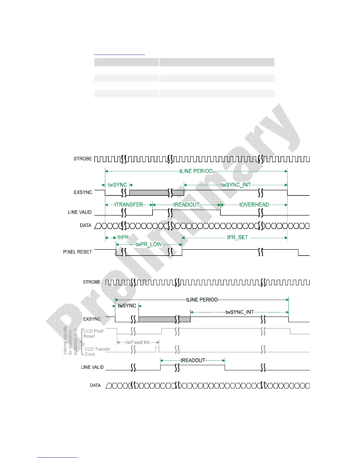
2.6 Camera Link Video Timing
Figure 11: Spyder 3 Overview Timing Showing Input and Output Relationships
Figure 12: Spyder 3 Fixed (Programmed) Integration Timing with External EXSYNC

 Loading...