CO2-Recovery Plant 16 EN/2020
2.6.8 Dehydrator
The dehydrators are extracting any unwanted liquids from the gas, the gas enters from the
bottom and passes through activated carbon, and after that passes through a very absorbent
desiccant – activated alumina. When the desiccant is close to reaching its maximum absorption
levels, they need to be dried. This is when the system changes to the second dehydrator and
initiate heating/drying on the first dehydrator. While one dehydrator is running, the other one is
regenerating. Designed by Kim Dalum.
Note: At some point maintenance is needed to change these orbs to keep the purity of the
product.
2.6.9 Sulfur filter
This is another stage for purification of the CO2. The sulfur filter lets the CO2 pass but filters
many other unwanted substances on the way through. This is designed by Kim Dalum and built
by Dalum Beverage Equipment.
2.6.10 Water separator
The water separators separate water from the gas, there is a separator for every stage on the
compressor. Designed by Kim Dalum and built by Dalum Beverage Equipment.
2.6.11 Liquid CO
2
collection tank
The Liquid CO2 collection tank is collection the liquid CO2 from the condenser, and when there
is enough it is discharged to the brewery’s CO2 storage tank. Designed by Kim Dalum and built
by Dalum Beverage Equipment.
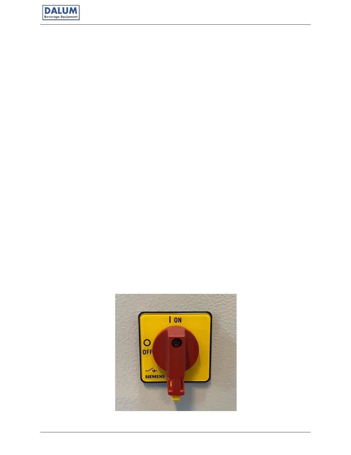
2.6.12 Main Switch
The main switch is located under the control panel. It serves two purposes: one as a
disconnecting means for service entrance and two as a disconnecting means for fault and
safety measures. If you suspect anything is wrong, power to the Unit can be disconnected by
this switch.