CO2-Recovery Plant 17 EN/2020
2.7 Electrical components
Most of the electrical components can be found in the electrical cabinet, but some are also
mounted in various places on the Unit. The DALUM CO2 Recovery Unit has both a high
voltage 230V circuit and low voltage 24V circuit.
2.7.1 Outside the electrical cabinet
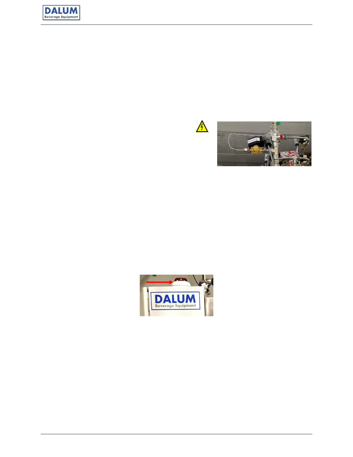
Solenoid valves – used to control flow from the PLC.
Note: The valves can be checked by observing that the light
comes on in the plug on the valve when the valve is
activated e.g., manually in Force ON. A noticeable CLICK
sound should be observed when the valve is turned on/off.
Note: Many of these valves have a high voltage connection, and they are marked with the
lightning warning sign.
Heating elements – used on the dehydrators. These are hidden by the isolation.
Note: Follow the temperatures of these on the Mimic Diagram in the PLC program.
Sensors – used in various places and for various purposes to make it possible for the Dalum
CO2 Unit to be self-diagnosing. Pressure, temperature, dewpoint, level, and rotation as some of
the conditions being monitored by sensors on the DALUM CO2 Unit.
Warning light – used to indicate when there is a fault, and the Unit needs attention.
Cooling water pump – generating flow in the cooling circuits (see picture in 2.6.3).