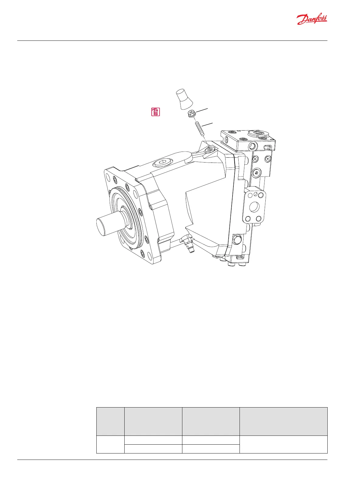
2. Discard the cap (Q120) after comparing it with a new one to make sure the new one fits.
Minimum displacement limiter
Q120
Tamper
resistant
cap
Y20
Y10
P101216E
3. Hold adjusting screw (Y10) using a 5 mm or 6 mm internal hex wrench.
4. Loosen the sealing lock nut (Y20), using a :
•
17 mm hex wrench for 060cm³ and 080cm³ frame size motors
or
•
19 mm hex wrench for 110cm³, 160cm³, and 250cm³ frame size motors.
5. Turn the adjustment screw (Y10) for the desired displacement (following the table) with a:
•
5 mm hex wrench for 060cm³ and 080cm³ frame size motors
or
•
6 mm hex wrench for 110cm³, 160cm³, and 250cm³ frame size motors.
Rotating the adjustment screw clockwise increases the minimum displacement of the motor; rotating
the adjustment screw counterclockwise decreases it.
The minimum displacement setting changes (see chart) for each full revolution of the adjustment
screw. Major changes in minimum displacement setting may require a different size adjustment
screw.
Adjustment screw and displacement
Frame size Minimum displacement
range cm³ [in³]
Screw size and length
mm [in]
Approximate change in minimum
displacement per revolution of
adjusting screw
cm³/rev [in³/rev]
60 12 - 29 [.73 - 1.77] M10 x 65 [2.56] 1.5 [.09]
30 - 36 [1.83 - 2.20] M10 x 80 [3.15]
Service Manual
Series 51 and 51-1 Motors
Adjustments
34 |
©
Danfoss | March 2016 11008567 | AX00000013en-US0202