Minimum angle adjustment screw
Disassembly
Warning
Improper adjustment of the minimum displacement limiter can result in undesirable or unsafe speed
conditions. Consult with the original equipment manufacturer or your Sauer-Danfoss representative
before changing the minimum displacement setting. After adjustment, verify the minimum displacement
setting by testing: using an appropriate test apparatus.
1. Thoroughly clean all external surfaces before disassembly.
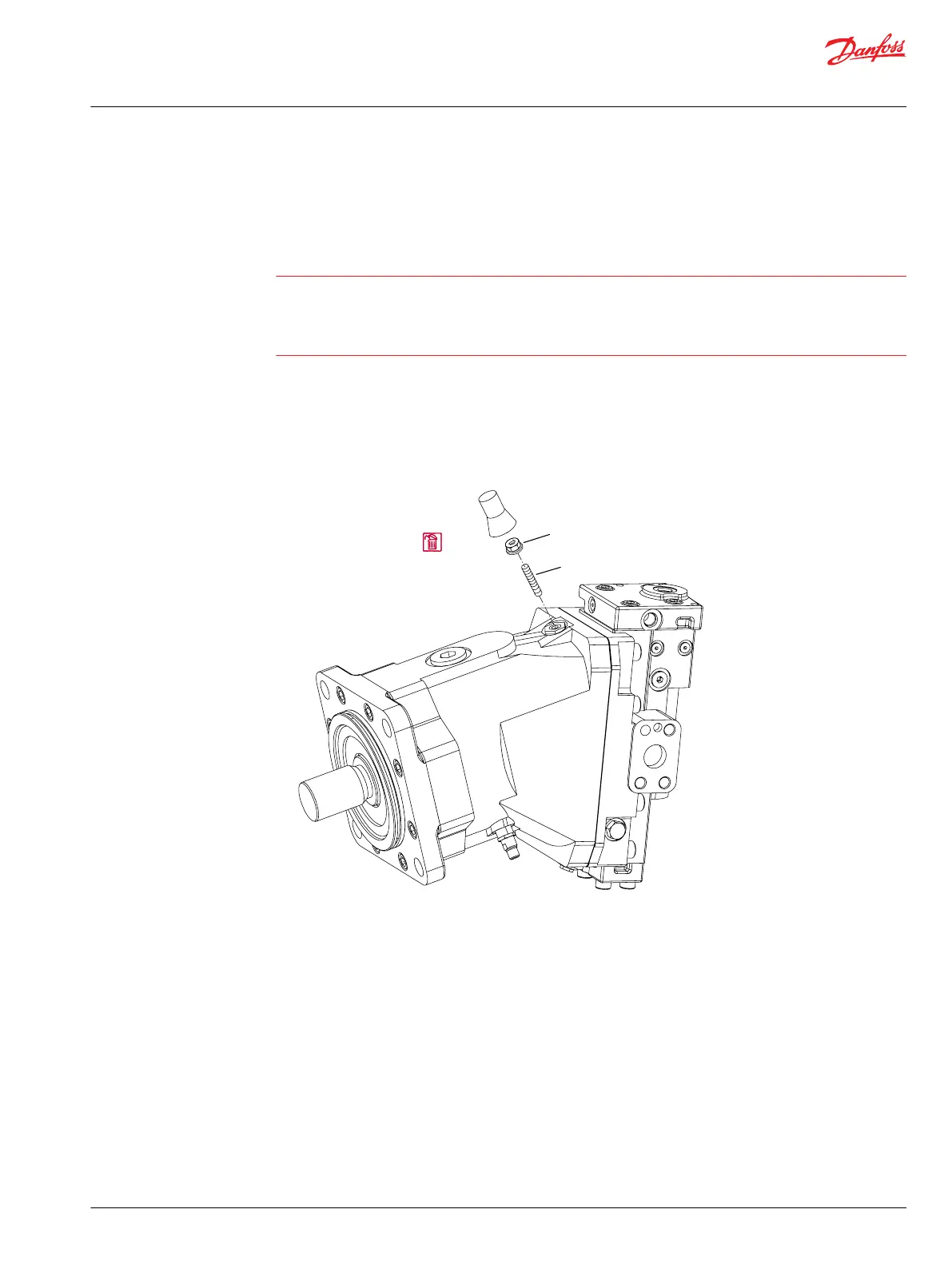
2. Remove the tamper resistant cap (Q120) covering the adjustment screw.
3. Discard the cap. Removing the cap destroys the locking device.
4. Measure the length of the screw (Y10) to assure correct reinstallation.
Minimum displacement limiter
Q120
Tamper
resistant
cap
Y20
Y10
P101216E
5.
Loosen the locknut (Y20) on the minimum angle adjustment screw using:
•
a 17 mm hex wrench for 60 cm³ and 80 cm³ motors
or
•
19 mm hex wrench for 110 cm³, 160 cm³ and 250 cm³ motors.
6. Remove the adjustment screw (Y10):
•
using a 5 mm hex wrench for 60 cm³ and 80 cm³ frame size motors
or
•
6 mm hex wrench for 110 cm³, 160 cm³ and 250 cm³ motors.
Inspection
Inspect the adjustment screw.
Service Manual
Series 51 and 51-1 Motors
Minor repair
©
Danfoss | March 2016 11008567 | AX00000013en-US0202 | 51

 Loading...


