3. After adjusting the plug, torque the locknut to 52 N•m [38 lbf•ft]. Do not overtorque
4. Remove the gauges.
5. Reinstall the port plugs.
Motors with loop flushing defeated, or equipped with an orificed charge pressure relief valve (see
Charge relief valve on page 44) do not require adjustment.
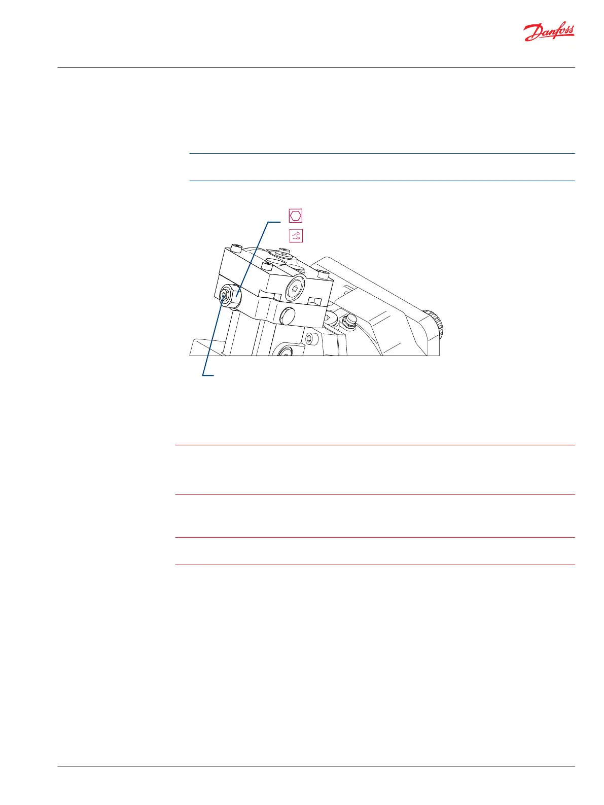
Series 51-1 charge pressure relief valve
1
1
/
16
inch
Adjustment plug
52 Nm [38 lbf•ft]
Minimum displacement limiter
Warning
Adjustment of the minimum displacement limiter can result in undesirable or unsafe speed conditions.
Consult with the Original Equipment Manufacturer or your Danfoss representative before changing the
minimum displacement setting. After adjustment, verify minimum displacement setting by using an
appropriate test apparatus.
The factory sets minimum displacement. A tamper-resistant cap covers the adjustment screw.
Caution
To avoid unexpected changes in operating conditions and to prevent external leakage, torque the lock
nut (Y20) after every adjustment.
Detect changes in motor displacement by providing a constant flow of fluid to the motor, while
maintaining the motor at minimum displacement and monitoring the motor output shaft speed. An
increase in displacement will result in a decrease in shaft speed, while a decrease in displacement will
result in an increase in shaft speed.
Adjusting minimum displacement
1. Remove the tamper resistant cap (Q120) from the adjusting screw (Y10). Removing the tamper
resistant cap destroys the locking device.
Service Manual
Series 51 and 51-1 Motors
Adjustments
©
Danfoss | March 2016 11008567 | AX00000013en-US0202 | 33