Required tools
You can perform service procedures described in this manual using common mechanic’s hand tools.
Special tools, if required, are shown. Calibrate pressure gauges frequently to ensure accuracy. Use
snubbers to protect pressure gauges.
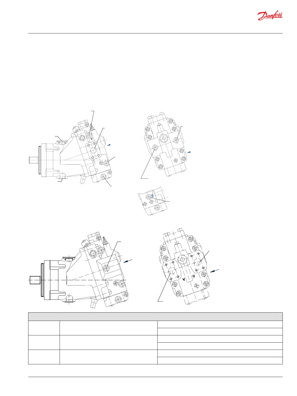
Port locations and gauge installation
Series 51 motors
P101 204Ea
System pressure B
Gauge port M2
Y
side port
Servo pressure supply for
maximum angle or
servo pressure maximum angle
Guage port M4
System pressure A
Gauge port M1
Main ports A+B
Servo supply
pressure
Guage port M5
Control pressure
Guage port M7
Alternate position
case drain L2
Servo pressure supply
for minimum angle or servo
pressure minimum angle
Guage port M3
Case drain L1
M1
M5
W
W
M3
Y
Side port
System pressure A+B
Guage port M1+M2
Axial port
Main
port B
Main
port A
M5
M3
M4
Y
W
Y
Axial port
P107 757E
Gauge information
M1 System pressure port A 600 bar [10,000 psi]
9/16-18 O-ring fitting
M2 System pressure port B 600 bar [10,000 psi]
9/16-18 O-ring fitting
M3 Servo pressure minimum angle 600 bar [10,000 psi]
9/16-18 O-ring fitting
Service Manual
Series 51 and 51-1 Motors
Pressure measurements
©
Danfoss | March 2016 11008567 | AX00000013en-US0202 | 23