Adjustment screw and displacement (continued)
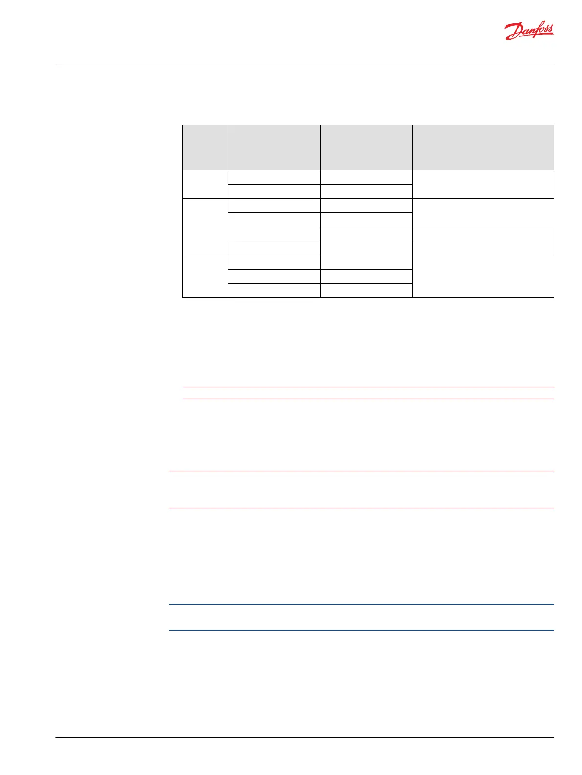
Frame size Minimum displacement
range cm³ [in³]
Screw size and length
mm [in]
Approximate change in minimum
displacement per revolution of
adjusting screw
cm³/rev [in³/rev]
80 16- 35 [.98 - 2.14] M10 x 65 [2.56] 2.1 [1.3]
36 - 54 [2.20 - 3.20] M10 x 80 [3.15]
110 22 - 46 [1.34 - 2.81] M12 x 70 [2.76] 3.1 [.19]
47 - 74 [2.878 - 4.52] M12 x 80 [3.15]
160 32 - 72 [1.95 - 4.39] M12 x 75 [2.95] 4.0 [.24]
73 - 107 [4.45 - 6.53] M12 x 90 [3.54]
250 50 - 90 [3.05 - 5.49] M12 x 75 [2.95] 6.2 [.38]
91 - 130 [5.55 - 7.93] M12 x 90 [3.54]
131 - 167 [7.99 - 10.19] M12 x 100 [3.94]
6. After adjustment, torque the lock nut on the adjustment screw to:
•
51 N•m [38 lbf•ft] for 060cm³ and 080cm³ motors
or
•
86 N•m [63 lbf•ft] for 110cm³, 160cm³, and 250cm³ motors.
Caution
Do not overtorque locknut
7. Install a new tamper-resistant cap.
Maximum displacement limiter
Warning
Adjusting the maximum displacement limiter can result in undesirable or unsafe speed conditions.
Consult with the Original Equipment Manufacturer or your Danfoss representative before changing the
maximum displacement setting.
Limit the maximum displacement by setting the stroke of the servo piston. A stop screw and spacer is on
the servo piston to limit the maximum displacement of the motor to less than 100%. Spacers are
available in 5% increments.
Limit the displacement by using spacers on the displacement stop screw. When changing the maximum
displacement, you may need a different length screw to accommodate the alternate spacers.
Detect changes in motor displacement by providing a constant flow of fluid to the motor, while
maintaining the motor at maximum displacement and monitoring the motor output shaft speed.
An increase in displacement results in a decrease in shaft speed. A decrease in displacement results in an
increase in shaft speed.
Service Manual
Series 51 and 51-1 Motors
Adjustments
©
Danfoss | March 2016 11008567 | AX00000013en-US0202 | 35