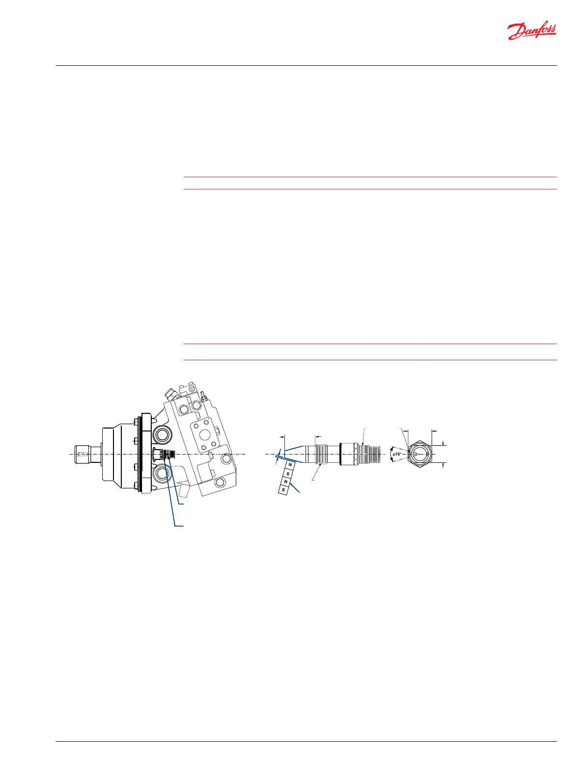
5. Continue backing out until the flats are 22° either side of the motor shaft center line (20° to 30° is
acceptable).
6. Hold sensor with a 1/2 inch wrench, torque the locknut using an 11/16 inch wrench to 13 N•m [10
lbf•ft].
Caution
Do not overtorque locknut.
Cartridge units
1. Loosen locknut.
2. Push O-ring toward connector end of sensor unit so that the O-ring does not contact motor housing
during step 3.
3. Thread sensor (CW) into motor housing by hand until bottom end touches the speed ring.
4. Back out (CCW) 2 turns.
5. Turn in or out (whichever is closest) until the orientation notch is 180° away from housing.
6. Hold sensor with a 1/2 inch wrench, torque the locknut using an 11/16 inch wrench to 13 N•m [10
lbf•ft].
Caution
Do not overtorque locknut.
Cartridge model speed sensor
Orientation
notch
Speed sensor
Speed ring
9/16-18UNF-2A thread
Air gap to be
1.52mm [0.060 in.]
max. approximate
2-3 turn of thread
Orientation
notch
22.9 [0.90]
11/16 in.
12.7 [0.50]
flats
P101 333E
Service Manual
Series 51 and 51-1 Motors
Adjustments
©
Danfoss | March 2016 11008567 | AX00000013en-US0202 | 39
 Loading...


