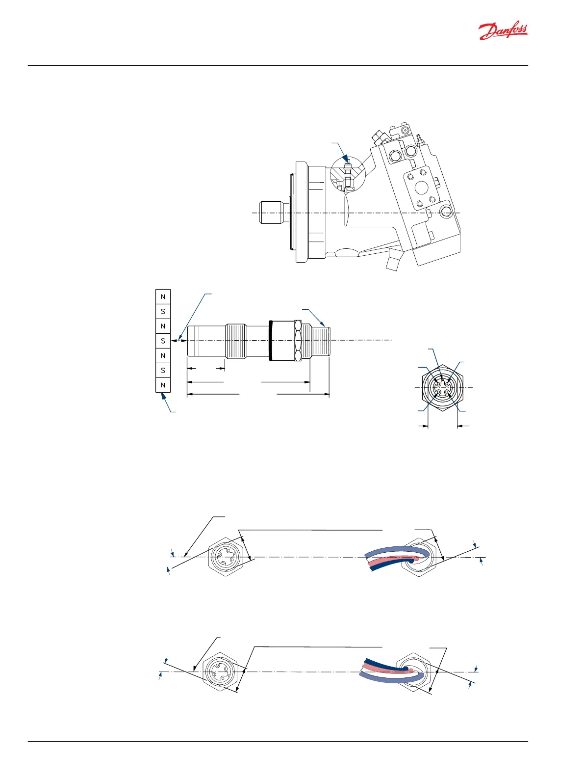
Speed sensor installation
Speed sensor
Air gap to be 1.52 [0.060] max.
(Approx. 1/2-1 turn of thread)
M12x1D6G thread
4 pin turck
Keyway ref.
Pin 2
direction
Pin 1
power +
Pin 3
speed
12.7 [0.50]
flats
Pin 4
ground
Speed
ring
61.2
[2.41]
50.8
[2.00]
16.2
[0.64]
P101334E
2. Push the O-ring toward connector end of sensor unit so that the O-ring does not contact motor
housing during step 3.
Speed sensor with Turck connector/Speed sensor with Packard connector
Shaft
centerline
1/2 inch
wrench flats
Shaft
centerline
1/2 inch
wrench flats
22°
22°
22°
22°
P101332Erev
3. Thread sensor (CW) into motor housing by hand until bottom end touches the speed ring.
4. Back out (CCW) 1/2 turn.
Service Manual
Series 51 and 51-1 Motors
Adjustments
38 |
©
Danfoss | March 2016 11008567 | AX00000013en-US0202
 Loading...


