2. Remove the control assembly.
3. Remove interface (G36) and O‑rings (G42) or seal plate.
4. Add appropriate spacer (F20) and screw to achieve the desired displacement (see chart below).
Using a longer spacer decreases the maximum displacement. Using a shorter spacer increases
maximum displacement.
5. Torque displacement limiter screw (F10) to:
•
46 N•m [34 lbf•ft] for the 80cm³ and 110cm³ motors.
•
23 N•m [17 lbf•ft] for the 60 cm³ motor.
Caution
Do not overtorque screws.
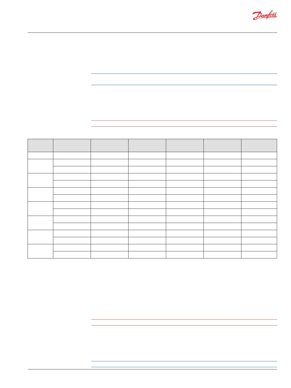
Maximum displacement screw (F10) and spacer (F20)
% of full
disp.
F10=screw
F20=spacer
60 cm³ 80cm³ 110cm³ 160cm³ 250cm³
100 F10N M8 x 20 M10 x 20 M10 x 20 M10 x 20 M10 x 20
95 F10A F8 x 25 M10 x 25 M10 x 25 M10 x 25 M10 x 25
F20A 3.5mm 4.0mm 4.0mm 4.5mm 5.0mm
90 F10B M8 x 25 M10 x 25 M10 x 30 M10 x 30 M10 x 30
F20B 6.5mm 7.5mm 8.0mm 9.0mm 10mm
85 F10C M8 x 30 M10 x 30 M10 x 30 M10 x 35 M10 x 35
F20C 9.5mm 11mm 11.5mm 13mm 15mm
80 F10D M8 x 30 M10 x 35 M10 x 35 M10 x40 M10 x 40
F20D 12.5mm 14.5mm 15mm 17mm 20mm
75 F10E M8 x 35 M10 x 40 M10 x 40 M10 x 40 M10 x 45
F20E 15.5mm 18mm 18.5mm 21mm 24.5mm
70 F10F M8 x 40 M10 x 40 M10 x 40 M10 x 45 M10 x 50
F20F 18.5mm 21mm 22mm 25mm 29mm
65 F10G M8 x 40 M10 x 45 M10 x 45 M10 x 50 M10 x 55
F20G 21.5mm 24.5mm 25.5mm 29mm 33.5mm
6. Replace all O-rings or seal plate. Do not discard any O-ring until you are certain that you have the
correct replacement.
7. Install the Series 51 minimum angle servo cover or Series 51-1 control.
8. Install the servo cover (G24) or control screws (M16).
9. Torque the servo cover control screws (M16) to:
•
78 N•m [58 lbf•ft] for 060cm³, 080cm³, 110cm³ and 160cm³ motors using an 8mm hex wrench.
•
110 N•m [81 lbf•ft] for 250cm³ motor using a 10mm hex wrench.
Caution
Do not overtorque screws.
Speed sensor installation and adjustment
DIN and SAE flange units
1. Loosen locknut.
Keep all old parts until you receive and inventory new parts.
Service Manual
Series 51 and 51-1 Motors
Adjustments
©
Danfoss | March 2016 11008567 | AX00000013en-US0202 | 37