use a 10 mm internal hex wrench
46 N•m [34 lbf•ft] for 80 cm³, 110 cm³, 160 cm³, 250 cm³ motors
Reassembly
1. Install the stop screw and spacer (if so equipped) to the servo piston end.
2. Torque the stop screw (F10) to:
•
23 N•m [17 lbf•ft] for a 60 cm³ motor using an 8 mm internal hex wrench
•
46 N•m [34 lbf•ft] for 80 cm³, 110 cm³, 160 cm³, and 250 cm³ motors using a 10mm internal hex
wrench.
3. Using petroleum jelly to retain them, install a new O-ring G100 and G36) to the end cap.
4. Install servo cover to (G260) the endcap.
5. Install the 4 screws (items G24).
6. Torque the 4 screws (G24) to:
•
78 N•m [58 lbf•ft] for 60cm³, 80cm³, 110cm³ and 160cm³ motors using an 8 mm internal hex
wrench.
•
110 N•m [81 lbf•ft] for 250cm³ motors using a 10mm internal hex wrench.
Caution
Do not overtorque screws
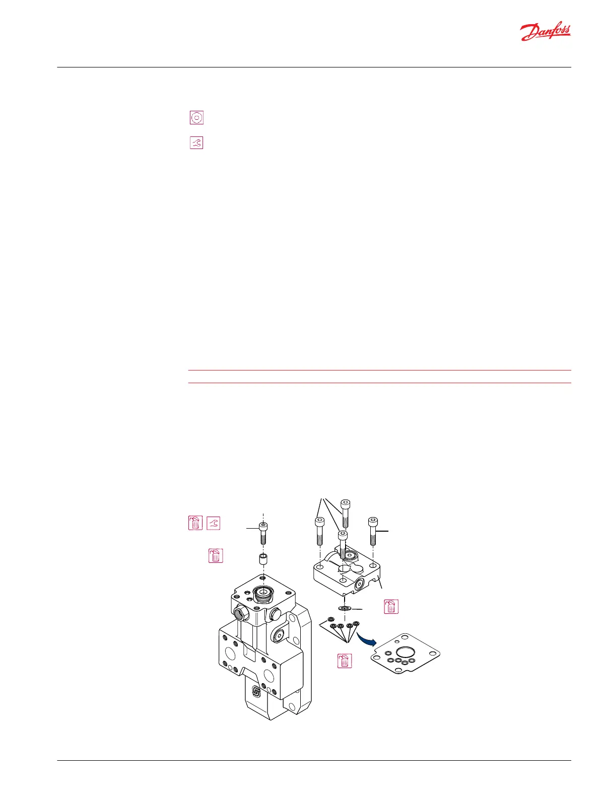
Maximum angle stop - Series 51-1 motors
Disassembly
1. Remove the 4 screws (M16) retaining the control assembly using an 8mm internal hex wrench.
2. Remove the control assembly.
Series 51-1 maximum displacement limiter
F10*
F20*
M16
M16
G42
G36
Control
P101 222E
or
Legend
F10
Service Manual
Series 51 and 51-1 Motors
Minor repair
©
Danfoss | March 2016 11008567 | AX00000013en-US0202 | 49