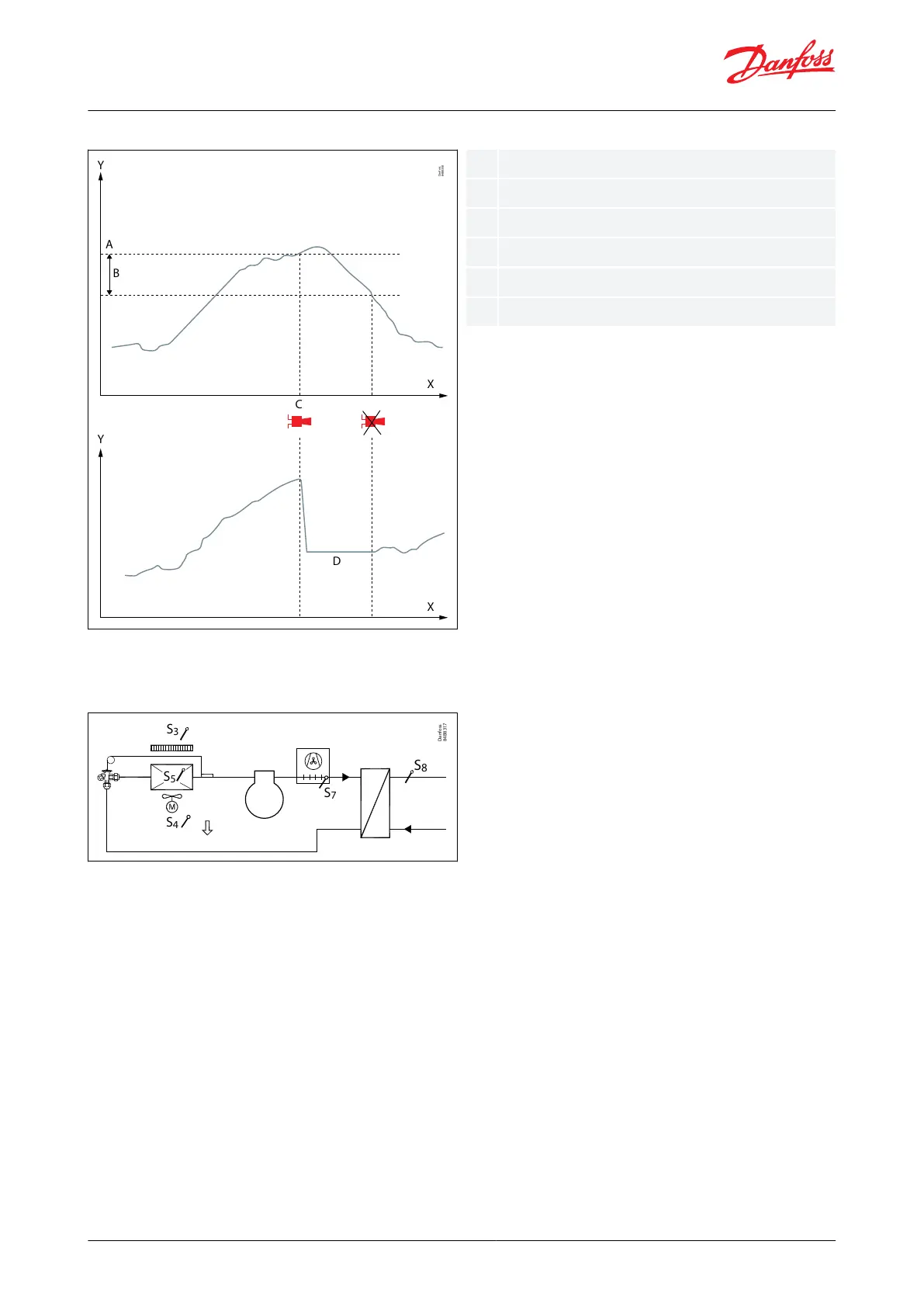
A77 Max. S7 Brine temp. di.
Figure 23: High S7 Brine inlet temperature
Condenser fan control (only with custom set-up)
On hybrid water loop systems an air-cooled condenser is also part of the refrigerant circuit, see Figure 24.
Figure 24: Condenser fan control
For such a hybrid system, the condenser fan can be congured for one of the outputs via the user dened
applications, and the S7 sensor can be used to control the condenser fan on/o. The S7 sensor is placed on the air-
cooled condenser to measure the condensing temperature. If the measured temperature increases above a set cut-
in limit, the condenser fan is started, and if the temperature decreases with a set dierential, the condenser fan is
stopped again.
Furthermore, a condenser fan override function can be dened for one of the digital inputs, so that the air-cooled
condenser can be used to provide heat to the store if needed.
© Danfoss | Climate Solutions | 2022.04 BC378540472015en-000101 | 17
AK-CC55 Water Loop