Cable length [m] AC line voltage [V] Rise time [usec]
V
peak
[kV]
dU/dt [kV/usec]
600 V 7.5 kW
5 525 0,192 0,972 4,083
50 525 0,356 1,32 2,949
5 600 0,184 1,06 4,609
50 600 0,42 1,49 2,976
Table 8.10
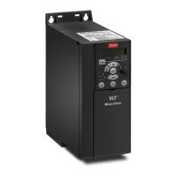
8.5 Derating according to Ambient
Temperature and Switching Frequency
The ambient temperature measured over 24 hours should
be at least 5
o
C lower than the max. ambient temperature.
If the frequency converter is operated at high ambient
temperature, the continuous output current should be
decreased.
110%
100%
90 %
80
%
70 %
60 %
50 %
40 %
30 %
20 %
10 %
0
I
out
[%]
0
2
5
10
16
40
o
C
50
o
C
45
o
C
fsw[kHz]
Illustration 8.1 200 V IP20 H1 0.25-0.75 kW
fsw [kHz]
20 10
0
10%
20%
30%
40%
50%
60%
70%
80%
90%
100%
110%
I
out [%]
16
40
45
50
5
o
C
o
C
o
C
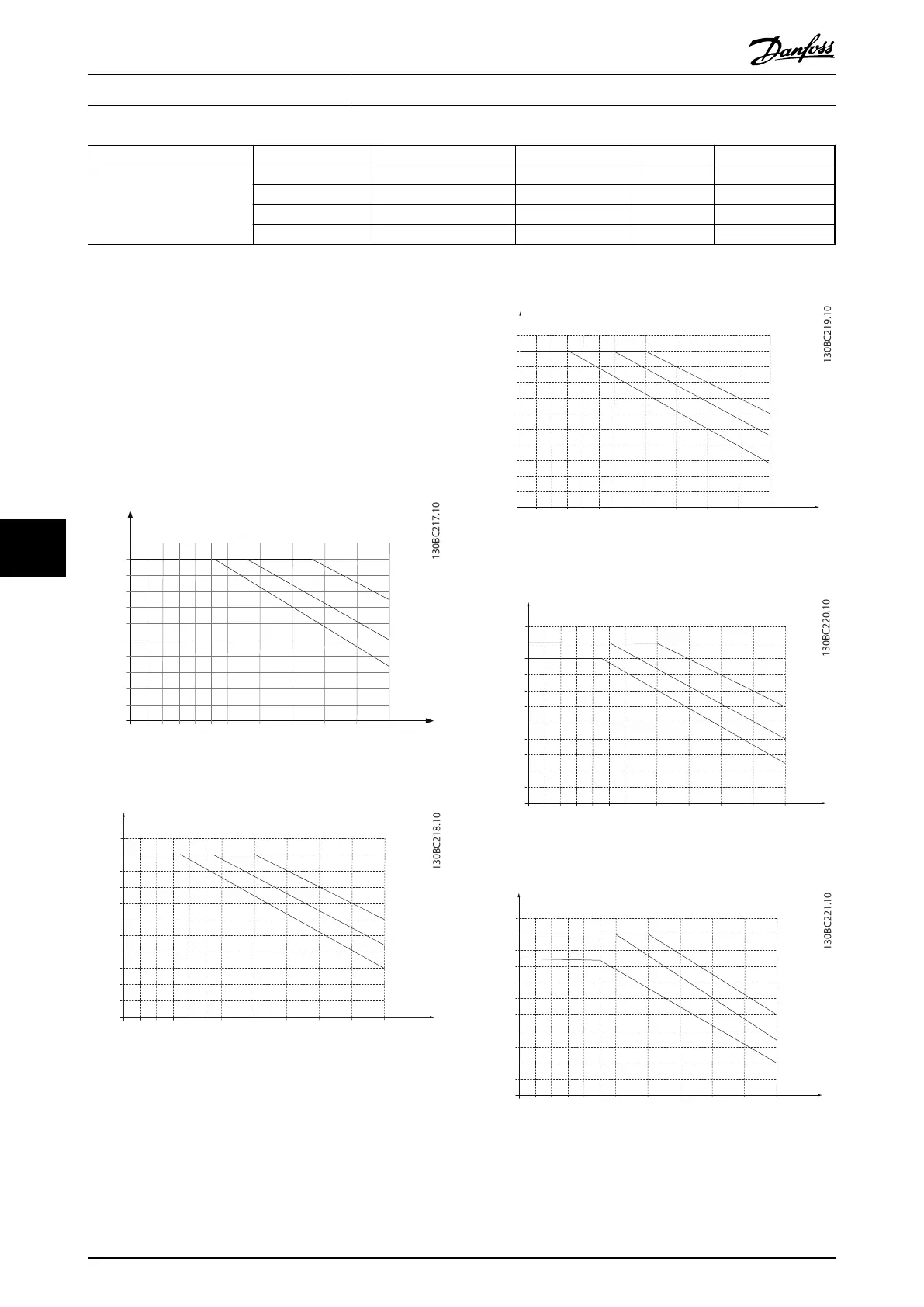
Illustration 8.2 400 V IP20 H1 0.37-1.5 kW
fsw[kHz]
20 10
0
10%
20%
30%
40%
50%
60%
70%
80%
90%
100%
110%
I
out[%]
16
40
45
50
5
o
C
o
C
o
C
Illustration 8.3 200 V IP20 H2 2.2 kW
fsw[kHz]
20 10
0
10%
20%
30%
40%
50%
60%
70%
80%
90%
100%
110%
I
out[%]
16
40
45
50
5
o
C
o
C
o
C
Illustration 8.4 400 V IP20 H2 2.2-4.0 kW
fsw[kHz]
20 10
0
10%
20%
30%
40%
50%
60%
70%
80%
90%
100%
110%
I
out[%]
16
40
45
50
5
o
C
o
C
o
C
Illustration 8.5 200 V IP20 H3 3.7 kW
General Specifications and ...
VLT
®
HVAC Basic Drive FC 101 Design Guide
112 MG18C502 - Rev. 2013-09-06
88