5.2.2 Connecting to Mains and Motor
The frequency converter is designed to operate all
standard 3-phased asynchronous motors. For maximum
cross-section on wires see 8.2 General Specifications.
•
Use a shielded/armored motor cable to comply
with EMC emission specifications, and connect
this cable to both the decoupling plate and the
motor metal.
•
Keep motor cable as short as possible to reduce
the noise level and leakage currents.
•
For further details on mounting of the
decoupling plate, see FC 101 De-coupling Plate
Mounting Instruction.
•
Also see EMC-Correct Installation in the VLT
®
HVAC
Basic Design Guide.
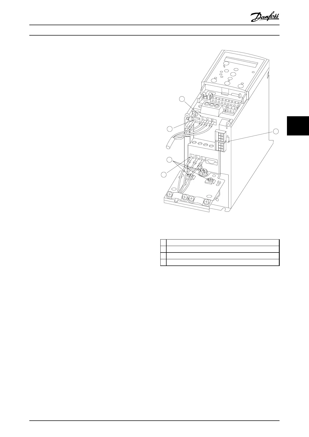
1. Mount the earth wires to earth terminal.
2. Connect motor to terminals U, V and W.
3. Mount mains supply to terminals L1, L2 and L3
and tighten.
130BB634.10
1
2
2
3
4
Motor
U
V
W
-DC
+DC
MAINS
Illustration 5.2 H1-H5 Frame
IP20 200-240 V 0.25-11 kW and IP20 380-480 V 0.37-22 kW
1
Line
2 Earth
3 Motor
4 Relays
Table 5.8 Legend to Illustration 5.2
How to Install
VLT
®
HVAC Basic Drive FC 101 Design Guide
MG18C502 - Rev. 2013-09-06 55
5 5