3.1.11.3 Electrical Wiring
MCB 114
Sensor Input Option B
SW. ver. xx.xx Code No. 130B1272
4-20mA
2 or 3
wire
2 or 3
wire
2 or 3
wire
2 or 3
wire
130BB326.10
Illustration 3.15 Electrical Wiring
Terminal Name Function
1 VDD 24V DC to supply
4-20mA sensor
2 I in 4-20mA input
3 GND Analog input GND
4, 7, 10 Temp 1, 2, 3 Temperature input
5, 8, 11 Wire 1, 2, 3
3
rd
wire input if 3 wire
sensors are used
6, 9, 12 GND Temp. input GND
Table 3.10 Terminals
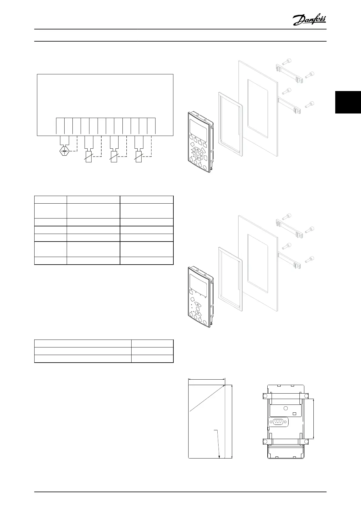
3.1.12
Remote Mounting Kit for LCP
The LCP can be moved to the front of a cabinet by using
the remote built-in kit. The enclosure is the IP66. The
fastening screws must be tightened with a torque of max.
1 Nm.
Enclosure IP66 front
Max. cable length between and unit 3 m
Communication std RS-485
Table 3.11 Technical Data
Illustration 3.16 LCP Kit with Graphical LCP, Fasteners, 3 m
Cable and Gasket
Ordering No. 130B1113
Illustration 3.17 LCP Kit with Numerical LCP, Fasteners and
Gasket
Ordering no. 130B1114
Max R2(0.08)
Panel
cut out
Min 72(2.8)
130BA139.11
129,5± 0.5 mm
64,5± 0.5 mm
(2.54± 0.04 in)
(5.1± 0.04 in)
Illustration 3.18 Dimensions
Selection Design Guide
MG11BC02 Danfoss A/S © Rev. 06/2014 All rights reserved. 61
3 3