6.1.5 Relay Connection
To set relay output, see parameter group 5-4* Relays.
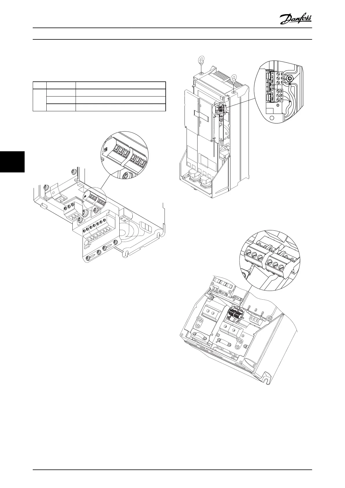
No.
01 - 02 make (normally open)
01 - 03 break (normally closed)
04 - 05 make (normally open)
04 - 06 break (normally closed)
Table 6.18 Description of Relays
130BA029.12
Relay2
Relay1
35 36
Illustration 6.36 Terminals for Relay Connection
(Enclosure Types A1, A2 and A3).
130BA391.12
RELAY 1 RELAY 2
06 05 04 03 02 01
DC+
Illustration 6.37 Terminals for Relay Connection
(Enclosure Types C1 and C2).
311
130BA215.10
RELAY 1
RELAY 2
9
9
6
03 02 01
90 05 04
Illustration 6.38 Terminals for Relay Connection
(Enclosure Types A5, B1 and B2).
Electrical Installation Design Guide
94 Danfoss A/S © Rev. 06/2014 All rights reserved. MG11BC02
66