General Purpose I/O
SW. ver. XX.XX
MCB 101
FC Series
Code No. 130BXXXX
B slot
X30/
AIN4
7 8654321 9 10 11 12
AIN3
GND(2)
24V
AOUT2
DOUT4
DOUT3
GND(1)
DIN7
COM
DIN
DIN8
DIN9
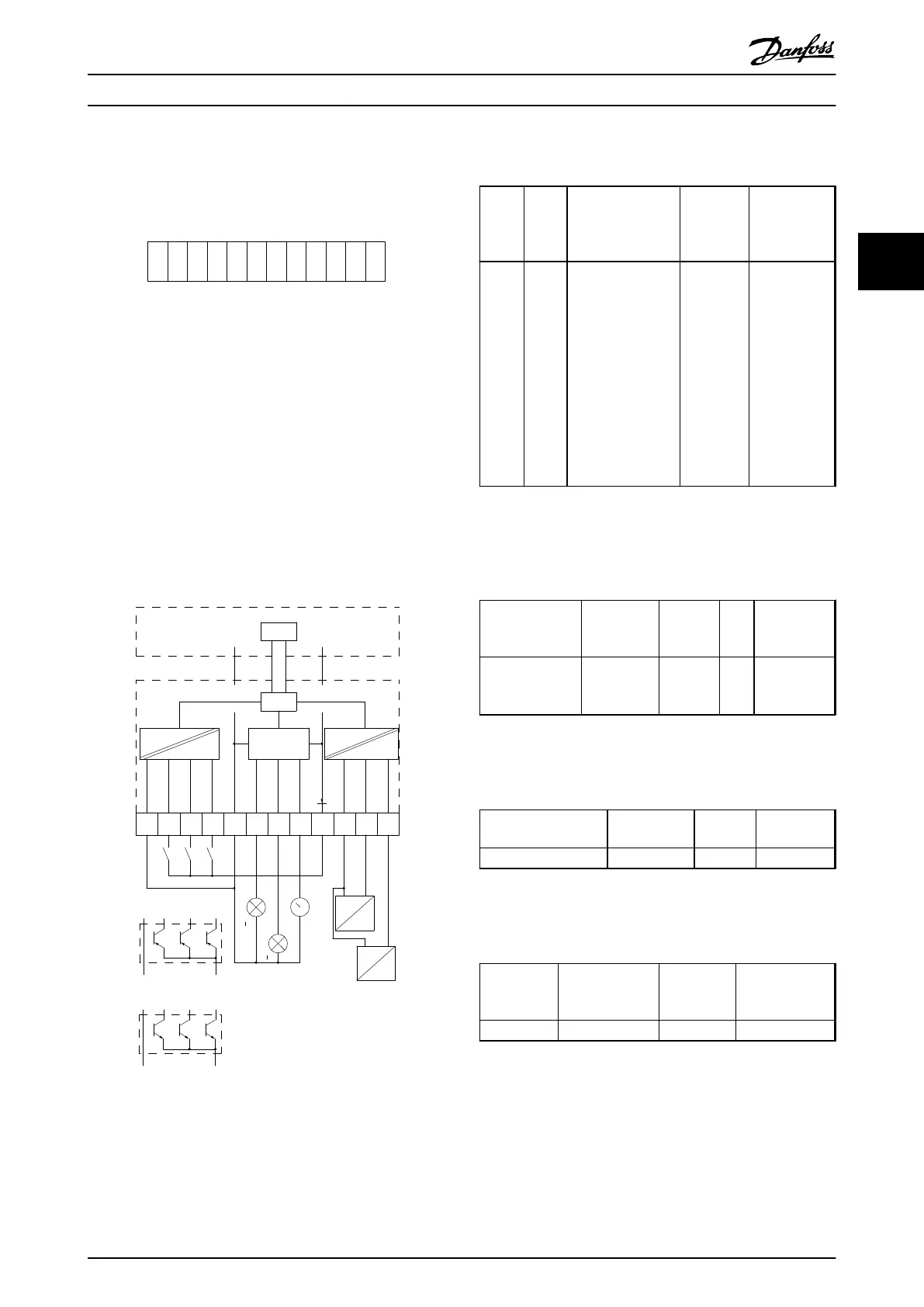
130BA208.10
Illustration 3.3
Galvanic isolation in the MCB 101
Digital/analog inputs are galvanically isolated from other
inputs/outputs on the MCB 101 and in the control card of
the frequency converter. Digital/analog outputs in the MCB
101 are galvanically isolated from other inputs/outputs on
the MCB 101, but not from these on the control card of
the frequency converter.
If the digital inputs 7, 8 or 9 are to be switched by use of
the internal 24 V power supply (terminal 9) the connection
between terminal 1 and 5 which is shown in Illustration 3.4
has to be established.
130BA209.10
1
2 3
4 5
6
7
8
9 10
11
12
COM DIN
DIN7
DIN8
DIN9
GND(1)
DOUT3
0/24VDC
DOUT4
0/24VDC
AOUT2
0/4-20mA
24V
GND(2)
AIN3
AIN4
RIN=
5kohm
RIN=
10kohm
0-10
VDC
0-10
VDC
0V 24V
0V 24V
24V DC0V
0V24V DC
<500 ohm
>600 ohm
>600 ohm
X30/
DIG IN
DIG &
ANALOG
OUT
ANALOG
IN
CPU
CAN BUS
CPU
Control card (FC 100/200/300)
General Purpose
I/O option MCB 101
PLC
(PNP)
PLC
(NPN)
Illustration 3.4 Principle Diagram
3.1.3
Digital Inputs - Terminal X30/1-4
Numb
er of
digital
inputs
Voltag
e level
Voltage levels Tolerance Max. Input
impedance
3 0-24 V
DC
PNP type:
Common = 0 V
Logic “0”: Input < 5
V DC
Logic “0”: Input >
10 V DC
NPN type:
Common = 24 V
Logic “0”: Input >
19 V DC
Logic “0”: Input <
14 V DC
± 28 V
continuous
± 37 V in
minimum
10 s
Approx. 5 kΩ
Table 3.1 Parameters for set-up: 5-16, 5-17 and 5-18
3.1.4
Analog Voltage Inputs - Terminal
X30/10-12
Number of
analog voltage
inputs
Standardised
input signal
Tolerance Reso
lutio
n
Max. Input
impedance
2 0-10 V DC
± 20 V
contin-
uously
10
bits
Approx. 5 KΩ
Table 3.2 Parameters for set-up: 6-3*, 6-4* and 16-76
3.1.5
Digital Outputs - Terminal X30/5-7
Number of digital
outputs
Output level Tolerance Max.impedan
ce
2 0 or 2 V DC
± 4 V ≥ 600 Ω
Table 3.3 Parameters for set-up: 5-32 and 5-33
3.1.6
Analog Outputs - Terminal X30/5+8
Number of
analog
outputs
Output signal
level
Tolerance Max. impedance
1 0/4 - 20 mA
±0.1 mA < 500 Ω
Table 3.4 Parameters for set-up: 6-6* and 16-77
Selection
Design Guide
MG11BC02 Danfoss A/S © Rev. 06/2014 All rights reserved. 53
3 3