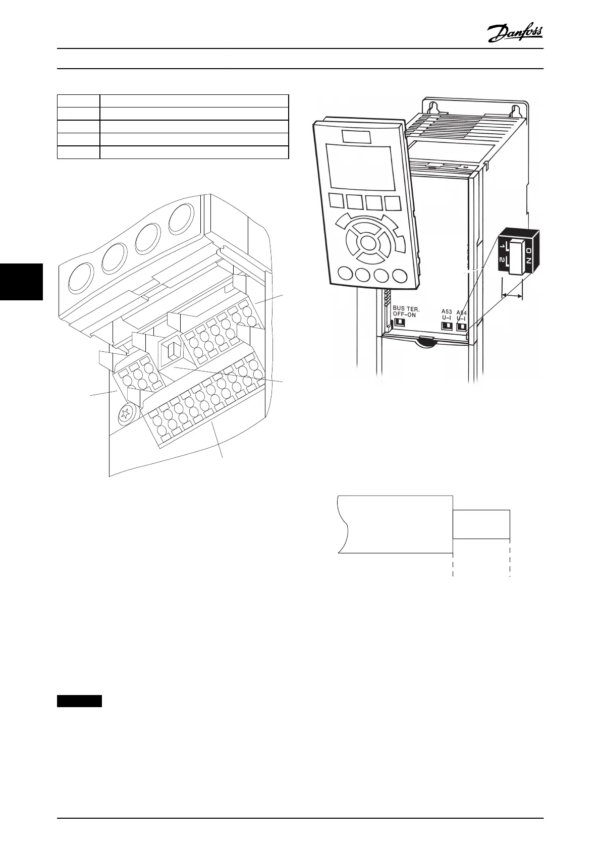
Item Description
1 10 pole plug digital I/O
2 3 pole plug RS-485 Bus
3 6 pole analog I/O
4 SB Connection
Table 6.39 Legend Table to Illustration 6.48, for FC 102
1
4
2
3
130BA012.12
61
68
69
39
42
50
53
54
55
12
13
18
19
27
29
32
33
20
37
Illustration 6.48 Control Terminals (all Enclosure Types)
6.5.4
Switches S201, S202, and S801
Switches S201 (A53) and S202 (A54) are used to select a
current (0-20 mA) or a voltage (-10 to 10 V) configuration
of the analog input terminals 53 and 54.
Switch S801 (BUS TER.) can be used to enable termination
on the RS-485 port (terminals 68 and 69).
Default setting
S201 (A53) = OFF (voltage input)
S202 (A54) = OFF (voltage input)
S801 (Bus termination) = OFF
NOTICE
When changing the function of S201, S202 or S801 be
careful not to use force for the switch over. It is
recommended to remove the LCP fixture (cradle) when
operating the switches. The switches must not be
operated with power on the frequency converter.
Illustration 6.49 Location of S201, S202 and S801 Switches
6.5.5
Electrical Installation, Control
Terminals
To mount the cable to the terminal
1. Strip insulation of 9-10 mm
130BA150.10
9 - 10 mm
(0.37 in)
Illustration 6.50 Strip Cable
2.
Insert a screwdriver
1)
in the square hole.
Electrical Installation
Design Guide
110 Danfoss A/S © Rev. 06/2014 All rights reserved. MG11BC02
66