Illustration 5.4 Proper Mounting with Railings
Item Description
1 Back plate
Table 5.5 Legend to Illustration 5.4
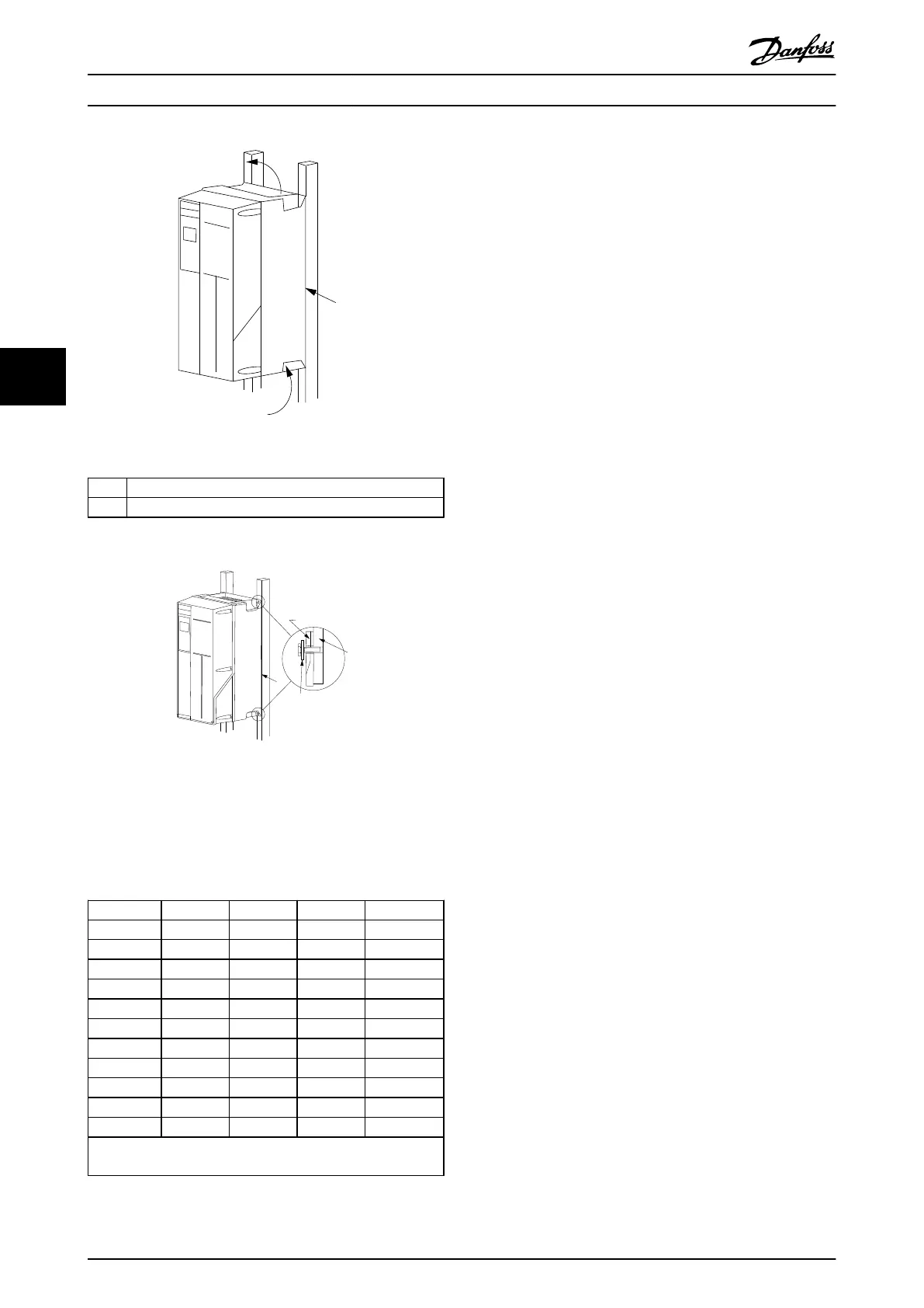
Illustration 5.5 Mounting on a Non-solid Back Wall
Mounting enclosure types A4, A5, B1, B2, C1 and C2 on a
non-solid back wall, the frequency converter must be
provided with a back plate, “1”, due to insufficient cooling
air over the heat sink.
Enclosure IP20 IP21 IP55 IP66
A2 * * - -
A3 * * - -
A4/A5 - - 2 2
B1 - * 2.2 2.2
B2 - * 2.2 2.2
B3 * - - -
B4 2 - - -
C1 - * 2.2 2.2
C2 - * 2.2 2.2
C3 2 - - -
C4 2 - - -
* = No screws to tighten
- = Does not exist
Table 5.6 Tightening Torque for Covers (Nm)
5.1.5
Field Mounting
For field mounting the IP21/IP4X top/TYPE 1 kits or IP54/55
units are recommended.
Mechanical Installation Design Guide
82 Danfoss A/S © Rev. 06/2014 All rights reserved. MG11BC02
55