7.1.14 Start/Stop Conditions
See 5-1* Digital Inputs.
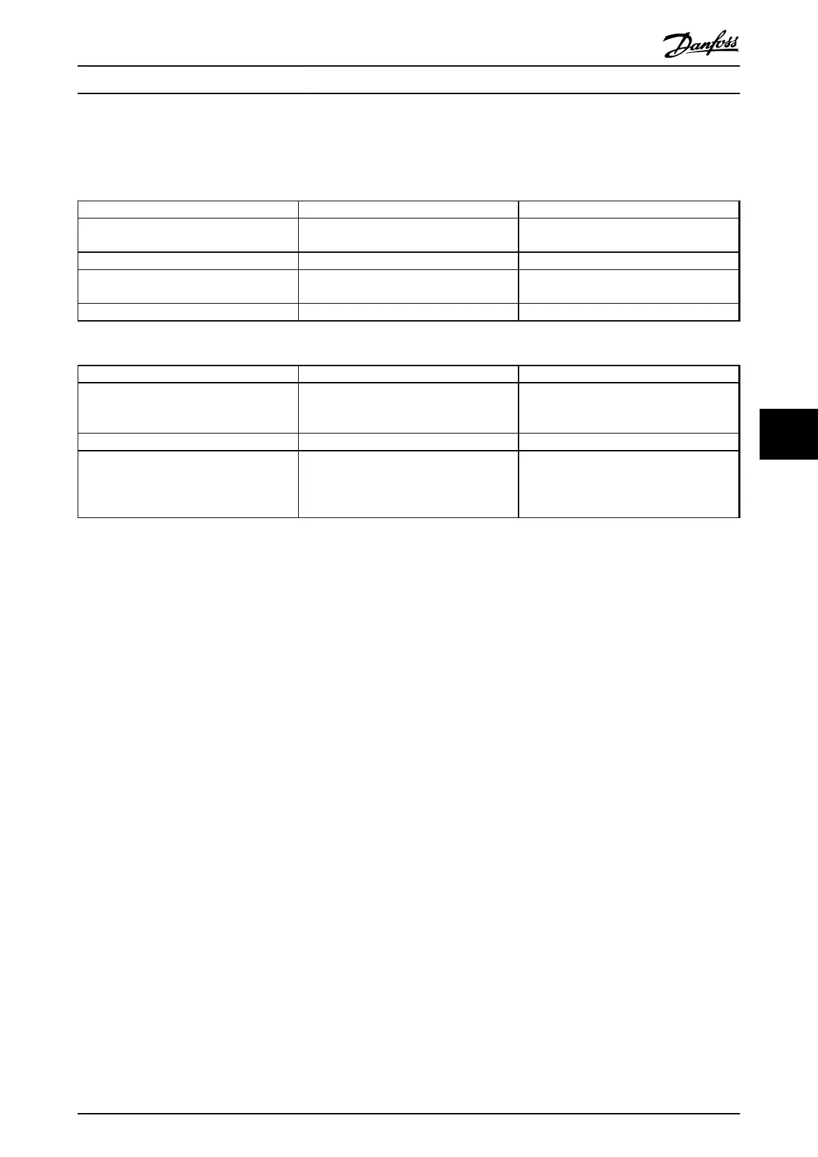
Digital input commands Variable speed pump (lead) Fixed speed pumps (lag)
Start (SYSTEM START/STOP) Ramps up (if stopped and there is a
demand)
Staging (if stopped and there is a demand)
Lead Pump Start Ramps up if SYSTEM START is active Not affected
Coast (EMERGENCY STOP) Coast to stop Cut out (correspond relays, terminal 27/29
and 42/45)
External Interlock Coast to stop Cut out (built-in relays are de-energised)
Table 7.1 Commands Assigned to Digital Inputs
LCP keys Variable speed pump (lead) Fixed speed pumps (lag)
[Hand On] Ramps up (if stopped by a normal stop
command) or stays in operation if already
running
Destaging (if running)
[Off] Ramps down Destaging
[Auto On] Starts and stops according to commands via
terminals or serial bus cascade controller
only can work when drive in "Auto ON"
mode
Staging/Destaging
Table 7.2 LCP Key Functions
Application Examples Design Guide
MG11BC02 Danfoss A/S © Rev. 06/2014 All rights reserved. 129
7 7