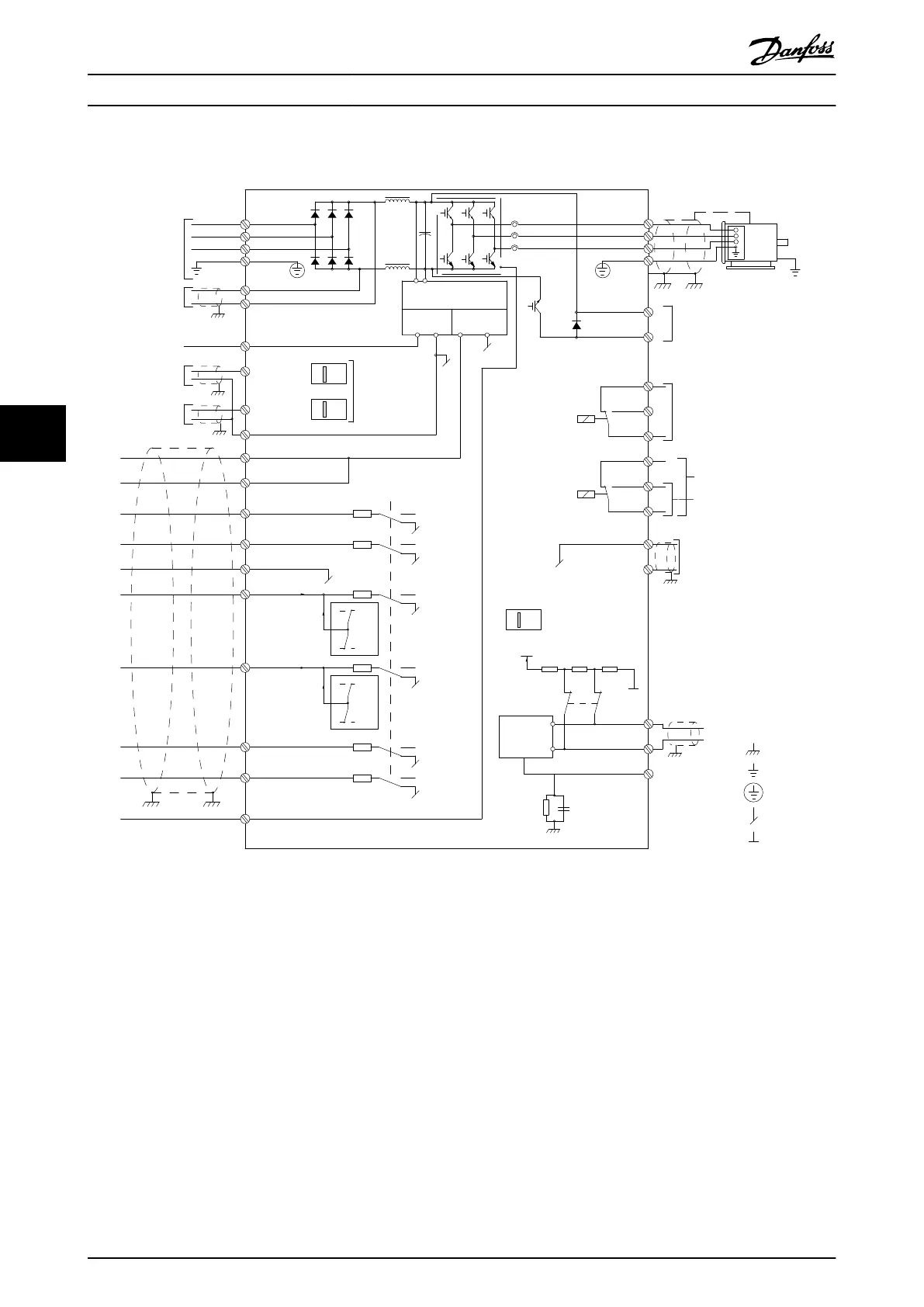
6.5.7 Electrical Installation, Control Cables
130BD552.12
3-phase
power
input
DC bus
Switch Mode
Power Supply
Motor
Analog Output
Interface
relay1
relay2
ON=Terminated
OFF=Open
Brake
resistor
91 (L1)
92 (L2)
93 (L3)
PE
88 (-)
89 (+)
50 (+10 V OUT)
53 (A IN)
54 (A IN)
55 (COM A IN)
0/4-20 mA
12 (+24 V OUT)
13 (+24 V OUT)
37 (D IN)
18 (D IN)
20 (COM D IN)
10 V DC
15 mA 200 mA
+ - + -
(U) 96
(V) 97
(W) 98
(PE) 99
(COM A OUT) 39
(A OUT) 42
(P RS-485) 68
(N RS-485) 69
(COM RS-485) 61
0 V
5V
S801
0/4-20 mA
RS-485
RS-485
03
+10 V DC
0/-10 V DC -
+10 V DC
+10 V DC
0/4-20 mA
0/-10 V DC-
240 V AC, 2 A
24 V DC
02
01
05
04
06
24 V (NPN)
0 V (PNP)
0 V (PNP)
24 V (NPN)
19 (D IN)
24 V (NPN)
0 V (PNP)
27
24 V
0 V
(D IN/OUT)
0 V (PNP)
24 V (NPN)
(D IN/OUT)
0 V
24 V
29
24 V (NPN)
0 V (PNP)
0 V (PNP)
24 V (NPN)
33 (D IN)
32 (D IN)
1 2
ON
A53
ON
21
A54
ON=0/4-20 mA
OFF=0/-10 V DC -
+10 V DC
95
P 5-00
21
ON
S801
(R+) 82
(R-) 81
: Chassis
: PE
**
240 V AC, 2 A
400 V AC, 2 A
*
: Ground 1
: Ground 2
: Ground
Illustration 6.55 Basic Wiring Schematic
A=Analog, D=Digital
*Terminal 37 (optional) is used for Safe Torque Off. For Safe Torque Off installation instructions, refer to the Safe Torque Off
Operating Instructions for Danfoss VLT
®
Frequency Converters.
**Do not connect cable screen.
Very long control cables and analog signals may in rare cases and depending on installation, result in 50/60 Hz ground
loops due to noise from mains supply cables. If this occurs, it may be necessary to break the screen or insert a 100 nF
capacitor between screen and chassis. The digital and analog inputs and outputs must be connected separately to the
common inputs (terminal 20, 55, 39) of the frequency converter to avoid ground currents from both groups to affect other
groups. For example, switching on the digital input may disturb the analog input signal.
Electrical Installation
Design Guide
112 Danfoss A/S © Rev. 06/2014 All rights reserved. MG11BC02
66