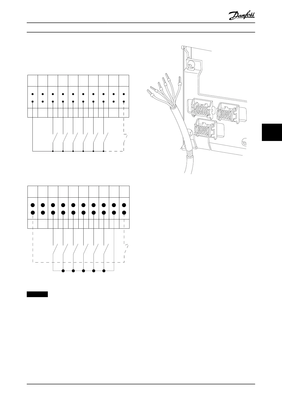
Input polarity of control terminals
12 13 18 19 27 29 32 33 20 37
+24 VDC
0 VDC
130BT106.10
PNP (Source)
Digital input wiring
Illustration 6.56 Input Polarity PNP (Source)
NPN (Sink)
Digital input wiring
12 13 18 19 27 29 32 33 20 37
+24 VDC
0 VDC
130BT107.11
Illustration 6.57 Input Polarity NPN (Sink)
NOTICE
To comply with EMC emission specifications, screened/
armoured cables are recommended. If an unscreened/
unarmoured cable is used, see chapter 2.9.2 EMC Test
Results.
Illustration 6.58 Grounding of Screened/Armoured Control
Cables
Electrical Installation Design Guide
MG11BC02 Danfoss A/S © Rev. 06/2014 All rights reserved. 113
6 6