130BA263.10
95
M
A
INS
+DC
BR-
BR+
U
V
W
91
92
93
L1
L2
L3
RELAY 1 RELAY 2
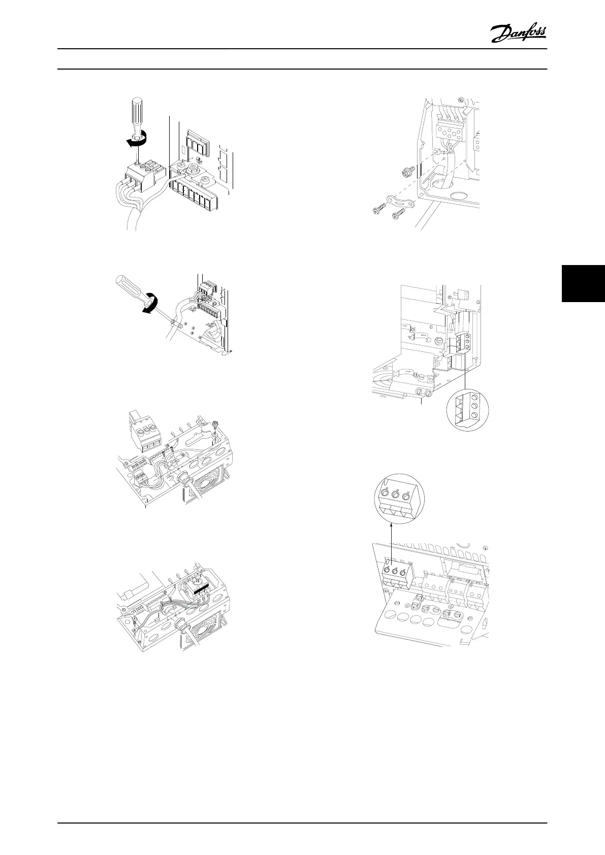
Illustration 6.4 Mounting Mains Plug and Tightening Wires
+DC
BR-
BR+
U
V
W
MAINS
L1 L2 L3
91 92 93
RELAY 1 RELAY 2
99
- LC -
130BA264.10
Illustration 6.5 Tighten Support Bracket
Mains connector enclosure type A4/A5 (IP55/66)
L 1
L 2
L 3
91
92
93
130BT336.10
Illustration 6.6 Connecting to Mains and Earthing without
Disconnector
Illustration 6.7 Connecting to Mains and Earthing with Discon-
nector
When disconnector is used (enclosure type A4/A5) the PE
must be mounted on the left side of the frequency
converter.
Illustration 6.8 Mains Connection Enclosure Types B1 and B2
(IP21/NEMA Type 1 and IP55/66/ NEMA Type 12)
Illustration 6.9 Mains Connection Enclosure Type B3 (IP20)
L1 91
L2 92
L3 93
L1 91
L2 92
L3 93
U 96
V 97
W 98
DC-88
DC+89
R-81
R+82
130BA714.10
95
99
Illustration 6.10 Mains Connection Enclosure Type B4 (IP20)
Electrical Installation Design Guide
MG11BC02 Danfoss A/S © Rev. 06/2014 All rights reserved. 85
6 6