0/4 mA
20 mA
50% 75% 100%0%
0% +100% +200%-200%
130BA856.10
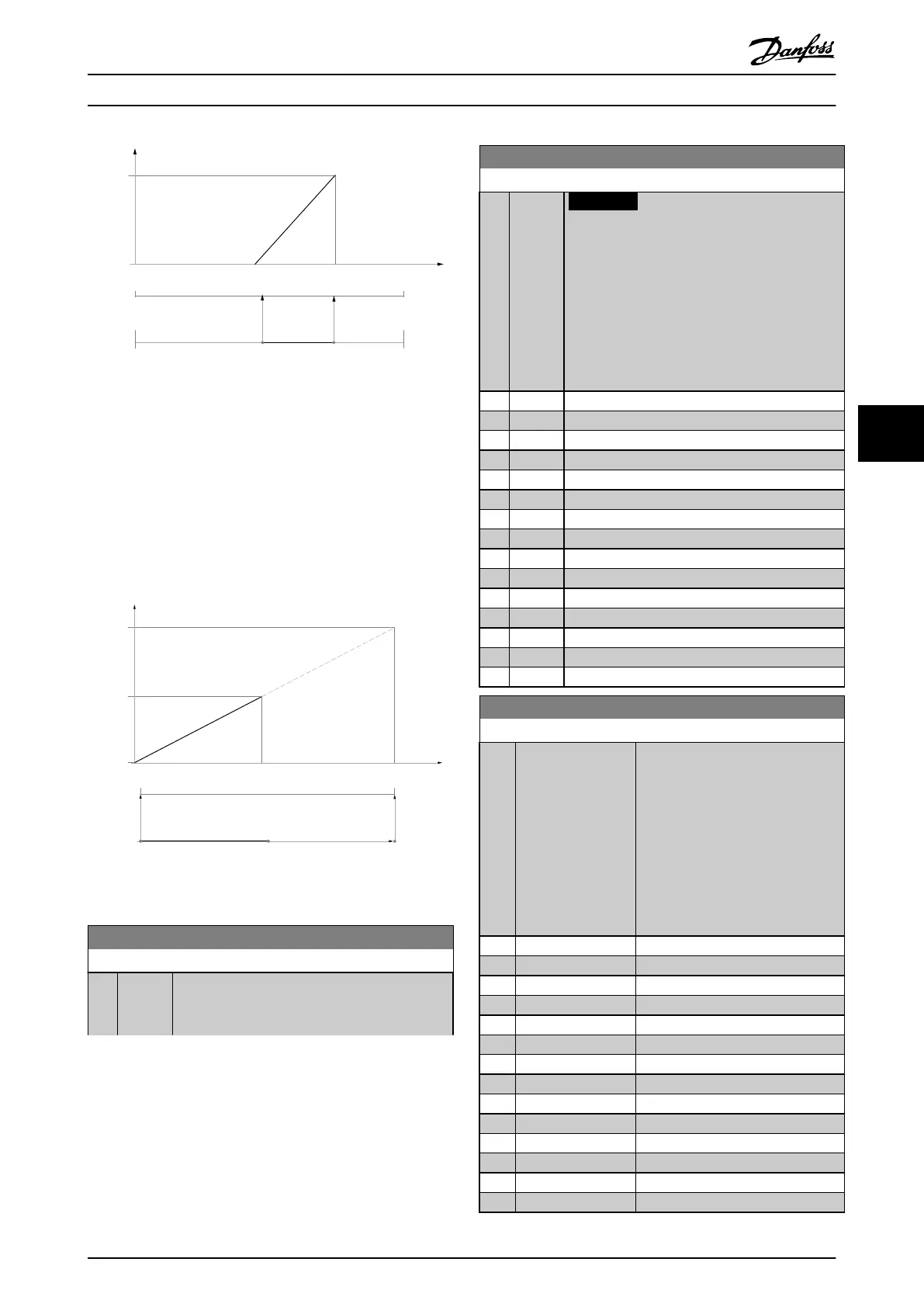
Illustration 6.15
Example 3:
Variable value= REFERENCE, range= Min ref - Max ref
Range needed for output= Min ref (0%) - Max ref (100%),
0-10 mA
Output signal 0 or 4 mA is needed at Min ref - set
parameter 6-51 Terminal 42 Output Min Scale to 0%
Output signal 10 mA is needed at Max ref (100% of range)
- set parameter 6-52 Terminal 42 Output Max Scale to 200%
(20 mA/10 mA x 100%=200%).
20 mA
10 mA
0/4 mA
100% 200%
0%
Max ref Max ref X 20/10Min ref
130BA857.10
Illustration 6.16
14-01 Switching Frequency
Option: Function:
Select the inverter switching frequency. Changing
the switching frequency can help to reduce
acoustic noise from the motor.
14-01 Switching Frequency
Option: Function:
NOTICE
The output frequency value of the
frequency converter must never exceed
1/10 of the switching frequency. When the
motor is running, adjust the switching
frequency in parameter 14-01 Switching
Frequency until the motor is as noiseless as
possible. See also 14-00 Switching Pattern
and the section Derating.
[0] 1.0 kHz
[1] 1.5 kHz
[2] 2.0 kHz
[3] 2.5 kHz
[4] 3.0 kHz
[5] 3.5 kHz
[6] 4.0 kHz
[7] 5.0 kHz
[8] 6.0 kHz
[9] 7.0 kHz
[10] 8.0 kHz
[11] 10.0 kHz
[12] 12.0kHz
[13] 14.0 kHz
[14] 16.0kHz
20-00 Feedback 1 Source
Option: Function:
Up to three different feedback
signals can be used to provide the
feedback signal for the frequency
converter’s PID Controller.
This parameter defines which input
will be used as the source of the
first feedback signal.
Analog input X30/11 and Analog
input X30/12 refer to inputs on the
optional General Purpose I/O board.
[0] No function
[1] Analog Input 53
[2] * Analog Input 54
[3] Pulse input 29
[4] Pulse input 33
[7] Analog Input X30/11
[8] Analog Input X30/12
[9] Analog Input X42/1
[10] Analog Input X42/3
[11] Analog Input X42/5
[15] Analog Input X48/2
[100] Bus Feedback 1
[101] Bus Feedback 2
[102] Bus feedback 3
How to Programme VLT HVAC Drive FC 102 Operating Instructions
MG11F402 - Rev. 2013-12-16 103
6 6
 Loading...


