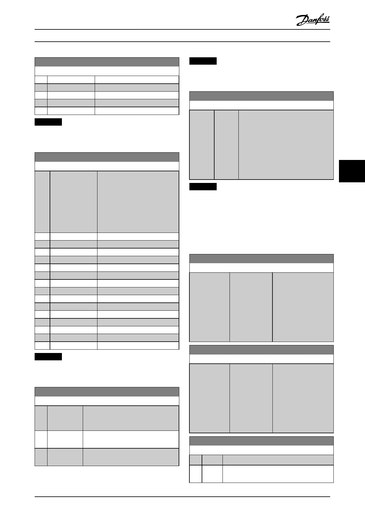
3-15 Reference 1 Source
Option: Function:
[25] Analog Input X42/5
[29] Analog Input X48/2
[30] Ext. Closed Loop 1
[31] Ext. Closed Loop 2
[32] Ext. Closed Loop 3
NOTICE
This parameter cannot be adjusted while the motor is
running.
3-16 Reference 2 Source
Option: Function:
Select the reference input to be
used for the second reference
signal. parameter 3-15 Reference 1
Source, parameter 3-16 Reference 2
Source and 3-17 Reference 3 Source
define up to 3 different reference
signals. The sum of these reference
signals defines the actual reference.
[0] No function
[1] Analog Input 53
[2] Analog Input 54
[7] Pulse input 29
[8] Pulse input 33
[20] * Digital pot.meter
[21] Analog input X30/11
[22] Analog input X30/12
[23] Analog Input X42/1
[24] Analog Input X42/3
[25] Analog Input X42/5
[29] Analog Input X48/2
[30] Ext. Closed Loop 1
[31] Ext. Closed Loop 2
[32] Ext. Closed Loop 3
NOTICE
This parameter cannot be adjusted while the motor is
running.
4-10 Motor Speed Direction
Option: Function:
Selects the motor speed direction required.
Use this parameter to prevent unwanted
reversing.
[0] Clockwise Only operation in clockwise direction is
allowed.
[2] * Both
directions
Operation in both clockwise and anti-
clockwise direction is allowed.
NOTICE
The setting in parameter 4-10 Motor Speed Direction has
impact on the Flying Start in parameter 1-73 Flying Start.
4-53 Warning Speed High
Range: Function:
Size
related*
[ par.
4-52 -
par. 4-13
RPM]
Enter the n
HIGH
value. When the motor
speed exceeds this limit (n
HIGH
), the display
reads SPEED HIGH. The signal outputs can
be programmed to produce a status signal
on terminal 27 or 29 and on relay output
01 or 02. Programme the upper signal
limit of the motor speed, n
HIGH
, within the
normal working range of the frequency
converter.
NOTICE
Any changes in parameter 4-13 Motor Speed High Limit
[RPM] reset the value in parameter 4-53 Warning Speed
High to the same value as set in parameter 4-13 Motor
Speed High Limit [RPM].
If a different value is needed in parameter 4-53 Warning
Speed High, it must be set after programming of
parameter 4-13 Motor Speed High Limit [RPM]
4-56 Warning Feedback Low
Range: Function:
-999999.999
ProcessCtrlUnit*
[ -999999.999 -
par. 4-57
ProcessCtrlUnit]
Enter the lower feedback
limit. When the feedback
falls below this limit, the
display reads Feedb
Low
.
The signal outputs can be
programmed to produce a
status signal on terminal
27 or 29 and on relay
output 01 or 02.
4-57 Warning Feedback High
Range: Function:
999999.999
ProcessCtrlUnit*
[ par. 4-56 -
999999.999
ProcessCtrlUnit]
Enter the upper feedback
limit. When the feedback
exceeds this limit, the
display reads Feedb
High
.
The signal outputs can be
programmed to produce a
status signal on terminal
27 or 29 and on relay
output 01 or 02.
4-64 Semi-Auto Bypass Set-up
Option: Function:
[0] * Off No function
[1] Enabled Starts the Semi-Automatic Bypass set-up and
continue with the procedure described above.
How to Programme VLT HVAC Drive FC 102 Operating Instructions
MG11F402 - Rev. 2013-12-16 97
6 6
 Loading...


