Service Monitor User Manual
Danfoss Turbocor Compressors Inc. 25
ECD-00007M Rev. 1
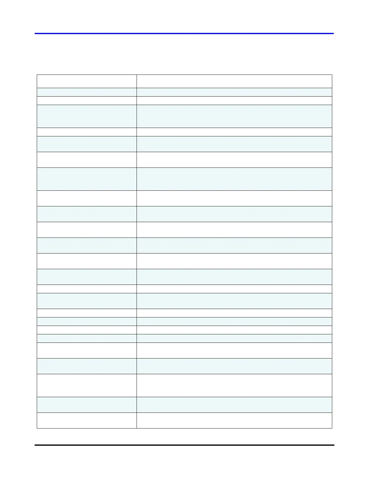
Table 6 Compressor Controller Parameters
Parameter Description
Te (on title bar) Evaporation Temperature
Tc (on title bar) Condensation Temperature
SH (on title bar) Superheat Calculation [Metric: ºK; Imperial: ºR]
If the absolute superheat value is < 5, then the gas is wet and will
cause the motor to overwork (as wet gas is heavier than dry gas).
Critical Faults Displays the compressor’s most recent active critical fault.
Refer to 6.3.2 "Compressor Faults/Alarms" for further details.
Compressor Alarms Displays the compressor’s most recent active critical alarm.
Refer to 6.3.2 "Compressor Faults/Alarms" for further details.
Compressor Control Mode Selects the source of demand for the compressor: Calibration, Manual
Control, Analog Input, Modbus Network, or Chiller Control. Refer to
6.3.1 "Compressor Control Modes" for further details.
Loading Demand (% max power) Compressor Demand: requested motor power demand as a
percentage of the maximum motor power [kW].
Inlet Guide Vane % of Inlet guide vane opening, 0.0% means the vanes are at 90º to the
pipe line (Fully closed). 110% means 10º over turned from fully open.
Suction Pressure The actual suction gauge pressure at the compressor flange as
measured by the suction pressure transducer.
Common Discharge Pressure Used when an extra discharge pressure transducer is mounted to a
common discharge line in the case of multiple compressors.
Discharge Pressure The actual discharge gauge pressure at the compressor flange as
measured by the discharge pressure transducer.
Suction Temperature The actual suction temperature at the compressor flange as measured
by the suction temperature/pressure transducer.
SCR Temperature Temperature of the SCR heat sink plate.
Discharge Temperature The actual discharge temperature at the compressor flange as
measured by the discharge temperature/pressure transducer.
Cavity Temperature Temperature of the superheated gas moving past the shaft.
Controller PCB Temperature Temperature of the BMCC circuit board.
Backplane Temperature Temperature of the backplane.
Stepper PCB Temperature Temperature of the serial driver circuit board.
Entering Air/water Temperature Temperature as measured by the 10K thermistor connected to the
terminals marked “ENTRY” on the Chiller Interface module.
Leaving Air/water Temperature Temperature as measured by the 10K thermistor connected to the
terminals marked “LEAVE” on the Chiller Interface module.
Interlock Contact Status of the digital input marked “I/LOCK” on the Chiller Interface
module. Possible values are “OPEN” and “CLOSED”. If condition is
open the compressor will not run.
External Pressure Gauge pressure as measured from a pressure transducer connected
to the terminals marked “SPARE P” on the Chiller Interface module.
External Temperature Temperature as measured from a thermistor connected to the
terminals marked “SPARE T” on the Chiller Interface module.

 Loading...


