Monitor Program Data and Controls
62 Danfoss Turbocor Compressors Inc.
ECD-00007M Rev. 1
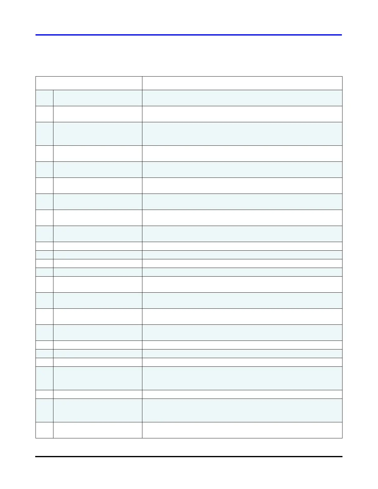
Table 22 List of Compressor Data Captured
Data Parameter Description
0 Compressor Control Faults Displays the compressor’s most recent active critical fault.
Refer to 6.3.2 "Compressor Faults/Alarms" for further details.
1 Compressor Control Alarms Displays the compressor’s most recent active critical alarm.
Refer to 6.3.2 "Compressor Faults/Alarms" for further details.
2 Compressor Control Mode Selects the source of demand for the compressor: either Calibration,
Manual Control, Analog Input, Modbus Network, or Chiller Control.
Refer to 6.3.1 "Compressor Control Modes" for further details.
3 Compressor Demand % Requested motor power demand as a percentage of the maximum
motor power [kW].
4 Inlet Guide Vane % Open % of Inlet guide vane opening, 0.0% means the vanes are at 90º to the
pipe line (Fully closed). 110% means 10º over turned from fully open.
5 Suction Pressure The actual suction gauge pressure at the compressor flange as
measured by the suction pressure transducer.
6 Discharge Pressure The actual discharge gauge pressure at the compressor flange as
measured by the discharge pressure transducer.
7 Suction Temperature The actual suction temperature at the compressor flange as measured
by the suction temperature/pressure transducer.
8 Discharge Temperature The actual discharge temperature at the compressor flange as
measured by the discharge temperature/pressure transducer.
9 Cavity Temperature Temperature of the superheated gas moving past the shaft.
10 Controller PCB Temperature Temperature of the BMCC board.
11 Backplane Temperature Temperature of the Backplane.
12 Stepper PCB Temperature Temperature of the Serial Driver.
13 Entering Water Temperature Temperature as measured from the 10K thermistor connected to the
terminals marked “ENTRY” on the Chiller Interface module.
14 Leaving Water Temperature Temperature as measured from the 10K thermistor connected to the
terminals marked “LEAVE” on the Chiller Interface module.
15 Estimated Minimum Speed
(compressor speed in RPM)
Estimated minimum RPM the compressor can run at with a fully open
inlet guide vane.
16 Maximum Speed
(compressor speed in RPM)
Maximum RPM the compressor can run at for a given set of inlet and
outlet conditions.
17 Display Units Metric / Imperial units displayed.
18 24VDC supply voltage Voltage outputted by 24VDC voltage supply.
19 EEV#1 Process Variable Controlled variable maintained by the stepper motor #1 output.
20 Stepper Motor #1 % Open Ratio of the actual number of steps sent to the stepper motor over the
maximum number of steps the motor is allowed to drive.
Range: 0%-100%.
21 EEV#2 Process Variable Controlled variable maintained by the stepper motor #2 output.
22 Stepper Motor #2 % Open Ratio of the actual number of steps sent to the stepper motor over the
maximum number of steps the motor is allowed to drive.
Range: 0%-100%.
23 Motor-Cooling Solenoids
Open
Number of motor-cooling solenoids open.

 Loading...


