•
•
•
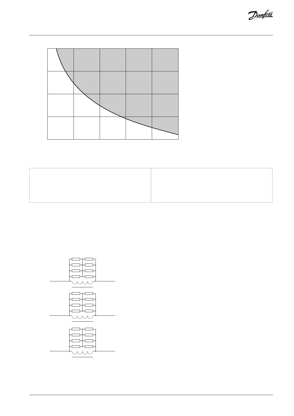
0.2I
ratio
0.4I
ratio
0.6I
ratio
0.8I
ratio
I
ratio
Illustration 14: Overcurrent Protection Setting Area
Rated input current of the drive
Time of the inrush current decay
The basic period: 20 ms for 50 Hz or 16.7 ms for
60 Hz
3.3.6 Output Filter Cabinet
The output filter cabinet is an optional cabinet which is connected at the output of the drive, between the inverter and motor. The
filter is used to:
Reduce the dU/dt of the voltage waveform.
Prevent resonance/overvoltage caused by motor cables.
Reduce the charging current of the cable.
L71-a
L71-b
L71-c
To
inverter
To
motor
R72A
R74A
R78A
R76A
R71A
R73A
R77A
R75A
R72B
R74B
R78B
R76B
R71B
R73B
R77B
R75B
R72C
R74C
R78C
R76C
R71C
R73C
R77C
R75C
e30bi652.10
Illustration 15: Output Filter Cabinet Circuit Diagram
Install the output filter cabinet between the drive and motor. The filter consists of a reactor and paralleling damping resistors. The
reactor decreases the rising edge of the PWM. The resistor damps the resonance caused by the reactor and stray inductance.
AQ363633621020en-000201 / 172F3117 | 23Danfoss A/S © 2021.06
Product Overview
VACON® 1000
Operating Guide