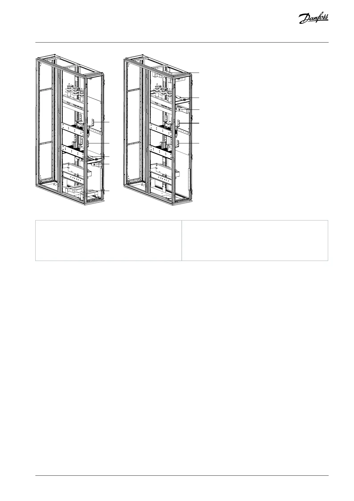
Illustration 47: Bottom Entry (Left) and Top Entry (Right)
Insulation barrier and supporting bracket
Cable clamp and supporting bracket
Clamp for three-core cable and supporting bracket
6.5.3 Power Cable Termination
Wiring kits including the recommended lugs, bolts, washers, and nuts are provided and delivered with cabinets.
Connect the lugs to the power cables and mount them to the input and output terminals with the parts included in the wiring kits.
6.5.4 Control Cable Entry
Both bottom entry and top entry are possible to the control cabinet. No modifications are required.
Once cable routing is finished, tie the control cables on the wire duct/bracket.
AQ363633621020en-000201 / 172F3117 | 51Danfoss A/S © 2021.06
Electrical Installation
VACON® 1000
Operating Guide

 Loading...


