3.4 System Operation
3.4.1 Main Circuit
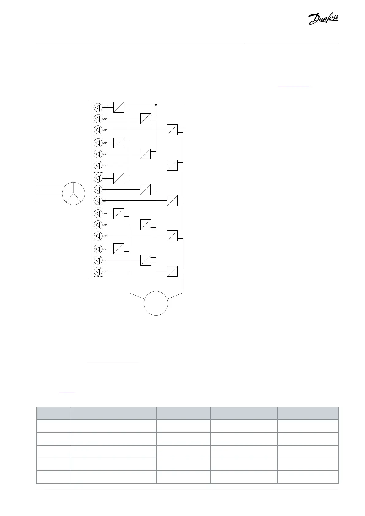
The typical main circuit topological structure diagram of VACON® 1000 medium-voltage drive is shown in Illustration 24.
Motor
Phase-shift
Transformer
Illustration 24: Main Circuit Diagram of VACON® 1000
The phase-shift rectifier transformer is a 3-phase air-cooled dry-type transformer directly connected with the incoming high voltage.
The secondary windings use an extended delta connection, which can lower the content of the input side current distortion. The
phase-shift angle between the secondary windings can be calculated according to the following formula:
Phase − shiftangle =
60°
Numberofpowercells
The secondary windings of the transformer provide input power for each power cell respectively. The number of secondary wind-
ings and the phase-shift angle between the windings are determined according to the voltage level and structure of the drive, as
shown in Table 2.
Table 2: Power Cell Configuration for VACON® 1000
Number of power cells per phase
AQ363633621020en-000201 / 172F3117 | 29Danfoss A/S © 2021.06
Product Overview
VACON® 1000
Operating Guide

 Loading...


