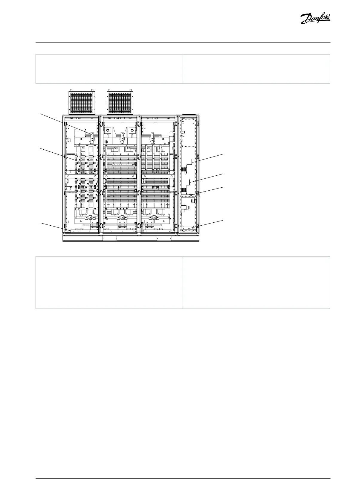
Busbars for connecting power cells in series
Output neutral point terminal
Transformer output terminal
Illustration 45: Terminals in the Transformer Cabinet
Transformer input terminal
Transformer output terminal
Grounding connection between cabinets
Power connection terminal
Motor connection terminal
System grounding terminal
6.5 Cable Entry and Termination
6.5.1 Power Cable Entry of Standalone Cabinet
Bottom entry and top entry are possible to the input/output cabinet. The cable routing is assembled for bottom entry or top entry
according to customer requirement.
AQ363633621020en-000201 / 172F3117 | 49Danfoss A/S © 2021.06
Electrical Installation
VACON® 1000
Operating Guide

 Loading...


