•
•
•
•
•
•
•
•
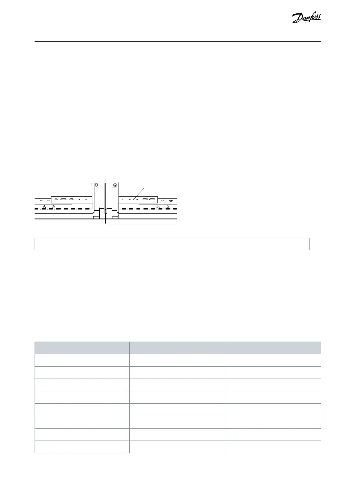
6.6 Grounding
Use interconnection busbars to connect the ground busbars in each cabinet.
In installations following the IEC standard, the cross-sectional area of the interconnection busbars must be at least:
Standalone type: 25 mm × 3 mm.
Lineup type <350 A: 40 mm × 3 mm.
Lineup type 350–680 A: 50 mm × 4 mm.
In installations following the UL standard, the cross-sectional area of the interconnection busbars must be at least 50 mm × 6 mm.
Connect the main grounding busbar of the cabinet to the system grounding cable. The recommended minimum cross-sectional
area for the connection is 95 mm
2
.
The cross-sectional area of the grounding cables must be ≥16 mm
2
and no more than half of the cross-sectional area of the high
voltage phase wires. In addition, the grounding resistance of the grounding connection must be lower than 4 Ω.
The ground leakage current value must be lower than 3.5 mA AC or 10 mA DC and must meet the safety specifications related to
high leakage current equipment.
The PE of the system grounding terminal must be grounded reliably to prevent accidents.
Do not use the same grounding wire with other power equipment or welding machine. Ground each drive independently where
there are multiple drives in the same room. Series connection to the ground is forbidden.
Illustration 50: Grounding Connection Between Cabinets
6.7 Power Cable Selection
Use armored three-core copper cable with XLPE or ERP insulation and metallic shield.
The wire sectional area recommended for the power and motor cables is based on the single-cable method of the three-core
cable and an ambient temperature of 40°C. If the conditions change (cable configuration, cable bundle, and ambient tempera-
ture), refer to the design information according to the cable configuration.
The highest temperature of the cables in the cabinet when operating continuously is 90°C.
The motor cable in the cabinet is copper-core with ethylene-propylene rubber insulation and chloroethene jacket.
If the input voltage is larger than the output voltage, the nominal voltage of the output power cable must be equal to the input
voltage.
Table 6: Recommended Power Cable Sizes
Input/output current rating
Conductor specification, IEC
Conductor specification, UL
AQ363633621020en-000201 / 172F3117 | 53Danfoss A/S © 2021.06
Electrical Installation
VACON® 1000
Operating Guide