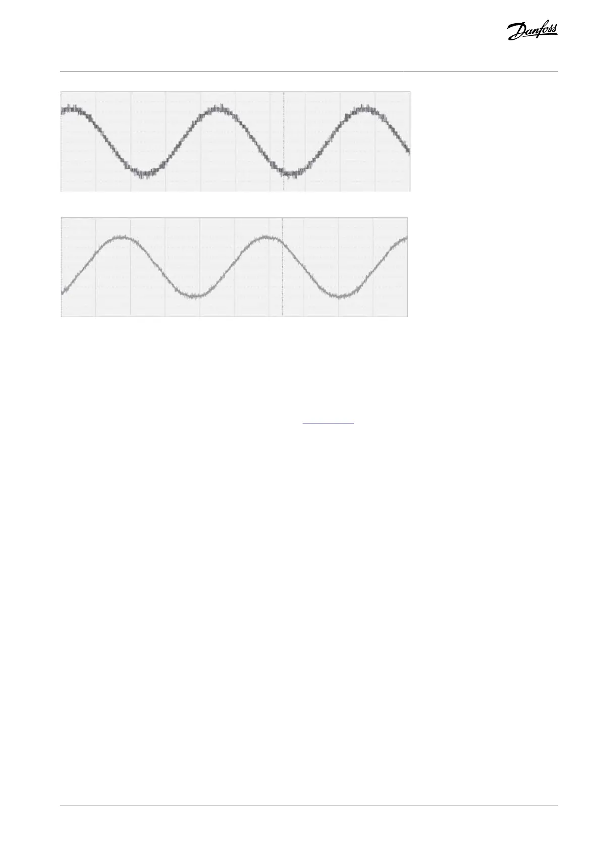
Illustration 26: Output Line-to-line Voltage Waveform
Illustration 27: Output Current Waveform
Each power cell has an independent cell control board and driver board. The cell control board receives the PWM signal transmitted
by the main control system through optical fiber to control the IGBT. Simultaneously, the status information of each power cell is
fed back to the main control system by the cell control board through optical fiber. The driver board is used to drive the IGBT and
feedback the failure signal of the IGBTs to the cell control board, such as short-circuit protection.
3.4.3 Control System
An example structure diagram of the control system is shown in Illustration 28. The number of power cells depends on the nominal
voltage of the drive.
AQ363633621020en-000201 / 172F3117 | 31Danfoss A/S © 2021.06
Product Overview
VACON® 1000
Operating Guide