•
•
•
•
•
•
•
•
•
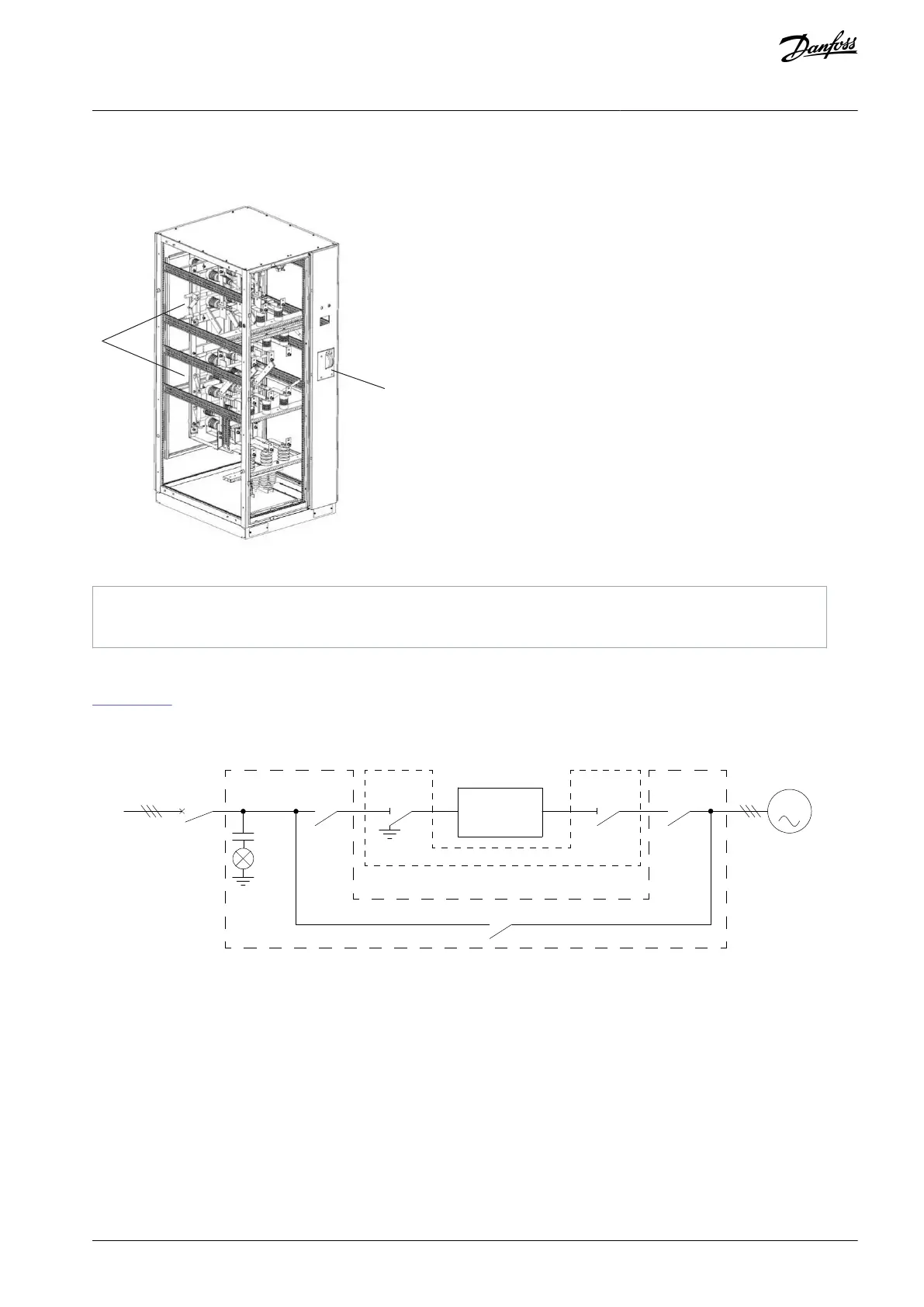
Realizes the electrical isolation between the phase-shift transformer and the power distribution system.
Provides the power frequency and variable frequency switching function and related electrical protection measures.
Illustration 18: Manual Bypass Cabinet
Dual-isolation switch panel
3.3.7.2 Automatic Bypass Cabinet
Illustration 19 shows an automatic bypass cabinet configuration, where:
KM41–KM43, high-voltage vacuum contactors.
QS41–QS42, manual separation knife switches.
HV~
MCB
M
Automatic bypass/Synchronous transfer cabinet
Manual bypass cabinet
QS41KM41 KM42
KM43
DN41
QS42
Drive
e30bi748.10
Illustration 19: Automatic Bypass Cabinet Circuit Diagram
When the drive is running:
QS41 and QS42 are closed.
KM41 and KM42 are closed.
KM43 is open.
When the drive is bypassed:
KM41 and KM42 are open.
KM43 is closed.
When maintenance is performed on the drive:
AQ363633621020en-000201 / 172F3117 | 25Danfoss A/S © 2021.06
Product Overview
VACON® 1000
Operating Guide
 Loading...


