•
•
•
•
•
•
•
•
•
•
•
•
•
•
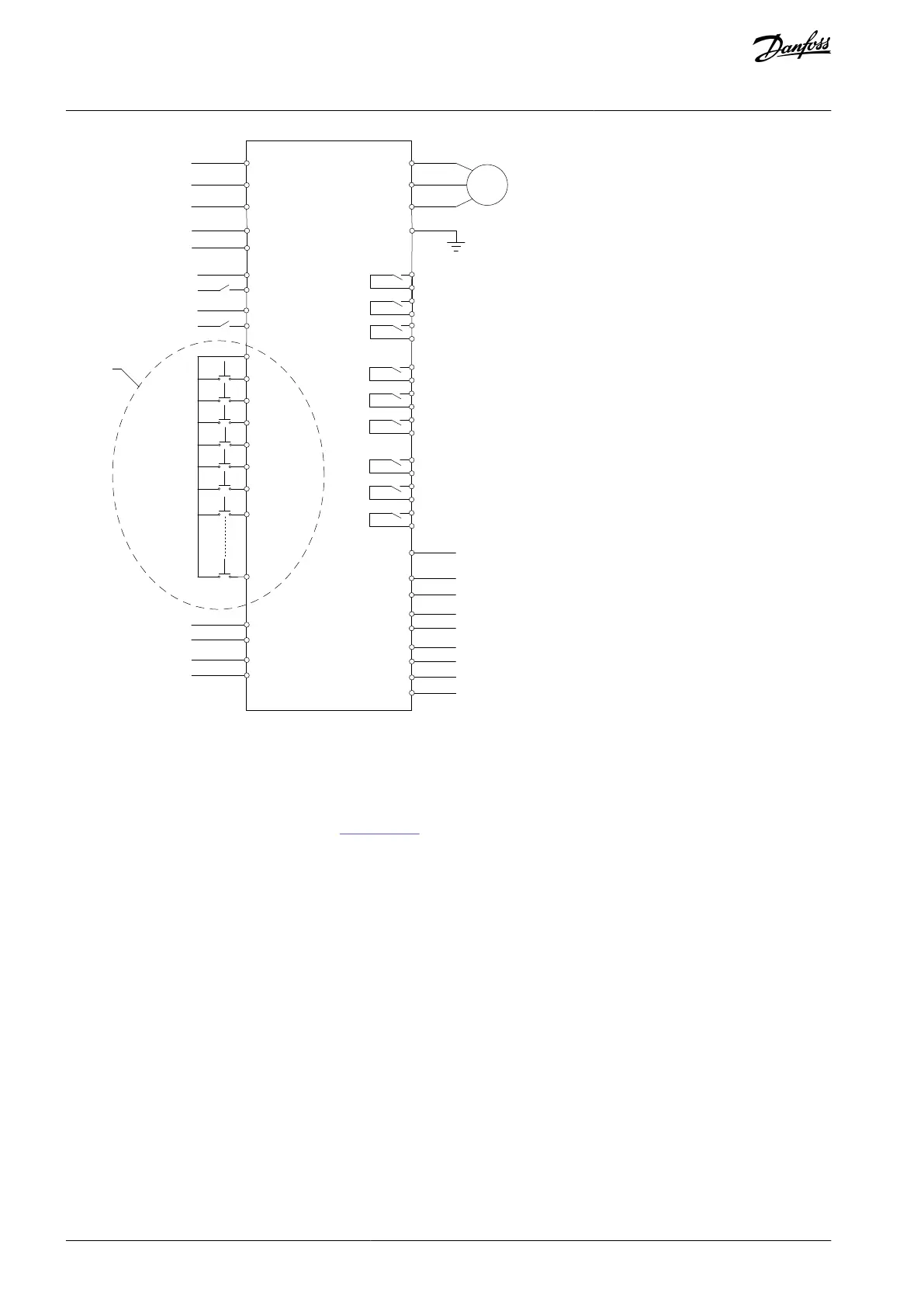
Main circuit
power input
L
N
Control power input
AC220V
Analog
output
Output current
Analog
input
MCB closed/open status
Exciting Current Feedback
from synchronous motor
Exciting current reference to
synchronous motor
Speed reference
Emergency stop E-stop
MCB closed/open status
2 (optional)
MCB trip 2(optional)
MCB trip
Illustration 51: Typical Application Wiring Diagram
6.9.5 PLC Configuration
6.9.5.1 PLC Basic Configuration
The basic configuration for the PLC is shown in Illustration 52.
Basic drive modules
C1: RS485 (Modbus RTU follower default)
DI_M: System control
DO_M: System control
DI: System control
TM1: Transformer
T31 temperature monitoring
DIDO1: Fan control 1
DIDO2: Fan control 2
DIDO3: Fan control 3
TM2: Transformer
T32 temperature monitoring
Standard option modules
DIDO4: Synchronous Transfer
DIDO5: Multi-motor selection/speed ramps selection/others
DIDO6: Excitation cabinet
AQ363633621020en-000201 / 172F311760 | Danfoss A/S © 2021.06
Electrical Installation
VACON® 1000
Operating Guide