•
•
•
504
415
415
415
415
415
415
415
415
415
415
415
KM43
KM41
KM41
KM42
KM43 closing coil
KM41 opening
coil
KM42 opening coil
KM43 opening coil
KM43 close switch
KM41 close switch
SF1
503
505
AC 220 V
Micro breaker
Fuse
PF auto transfer switch
VF to PF manual transfer switch SF2
PF to VF manual transfer switch SF2
KA2 self-lock circuit
Operation mode switch SF1
KM41 open push button SB1
KM43 open push button SB3
KM42 close push button SA2
KM41 close push button SA1
KM42 open command
KM43 open command
KM42 open push button SB2
KM43 close command
KM41 close command
KM42 close command
Time relay
Time relay circuit
KM43 close push button
KM42 close coil
KM41 close coil
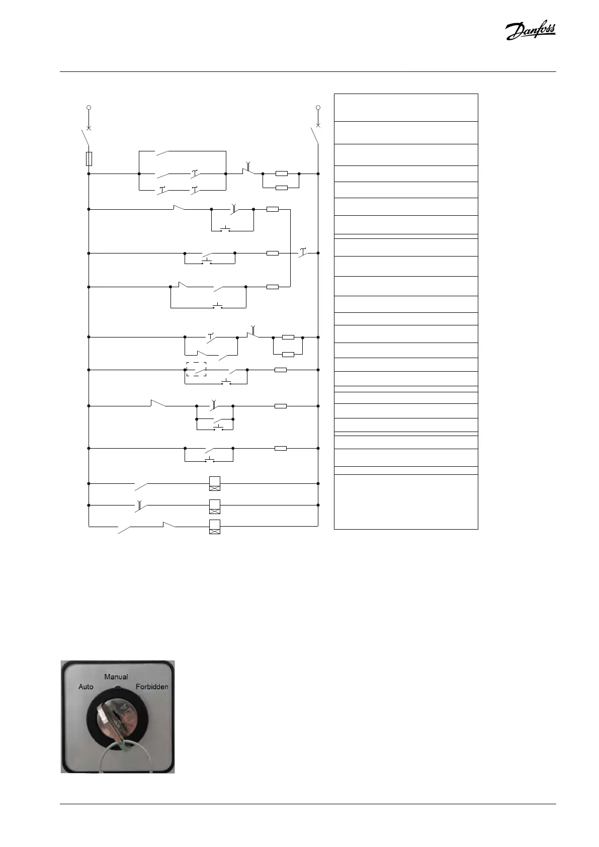
Illustration 20: Secondary Control Logic Diagram of VF Switching to PF
Operation Mode Switches
Switch SF1 is used to select the working mode to prevent incorrect operation.
Auto: Allows switching to PF bypass automatically when the drive is in a serious fault.
Manual: Allows manual switching to working-frequency bypass according to the real production requirements when the drive is
normally running.
Forbidden: If the production conditions do not allow the switching to working-frequency bypass, this mode can be selected to
prevent incorrect operation.
Illustration 21: Working Mode Selection Switch SF1
AQ363633621020en-000201 / 172F3117 | 27Danfoss A/S © 2021.06
Product Overview
VACON® 1000
Operating Guide

 Loading...


