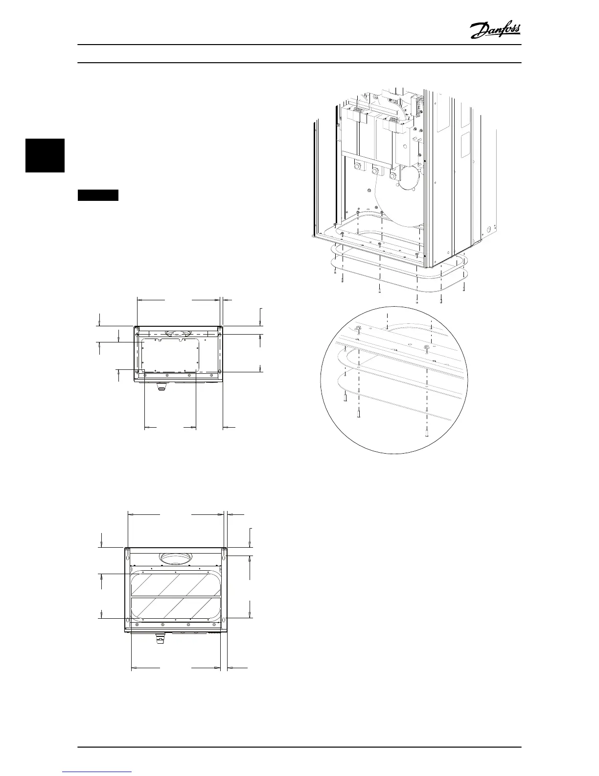
3.2.5 Gland/Conduit Entry - IP21 (NEMA 1)
and IP54 (NEMA12)
Cables are connected through the gland plate from the
bottom. Remove the plate and plan where to place the
entry for the glands or conduits. Illustration 3.12 and
Illustration 3.13 show the gland plate openings in bottom
views.
NOTICE
The gland plate ensures the specified protection degree,
and enables proper cooling of the unit. If the gland plate
is not mounted, the unit may trip on Alarm 69, Pwr. Card
Temp.
55.9
[2.2]
257.0
[10.1]
21.9
[.9]
560.0
[22.0]
110.6
[4.4]
182.8
[7.2]
181.9
[7.2]
350.0
[13.8]
130BC640.10
Illustration 3.12 Enclosure Size D14, Bottom View
361.7
[14.2]
20.0
[.8]
560.0
[22.0]
154.8
[6.1]
257.6
[10.1]
40.0
[1.6]
520.0
[20.5]
48.9
[2]
Illustration 3.13 Enclosure Size E1, Bottom View
Illustration 3.14 Mounting of Base Plate, E1
The base plate of the enclosure size E can be mounted
from either inside or outside of the enclosure, allowing
flexibility in the installation process. If mounted from the
bottom, the glands and cables can be mounted before the
unit is placed on the pedestal.
Mechanical Installation Operating Instructions
14 Danfoss A/S © 09/2014 All rights reserved. MG90V302
33