7 RS485 Installation and Set-up
7.1 Installation and Set-up
7.1.1 Overview
RS485 is a 2-wire bus interface compatible with multi-drop
network topology. Nodes can be connected as a bus, or
via drop cables from a common trunk line. A total of 32
nodes can be connected to one network segment.
Network segments are divided by repeaters. Each repeater
functions as a node within the segment in which it is
installed. Each node connected within a given network
must have a unique node address across all segments.
Terminate each segment at both ends using either the
termination switch (S801) of the unit, or a biased
termination resistor network. Use screened twisted pair
(STP) cable for bus cabling, and follow good common
installation practice.
Low-impedance ground connection of the screen at every
node is very important, including at high frequencies. This
can be achieved by connecting a large surface of the
screen-to-ground, for example with a cable clamp or a
conductive cable gland. It may be necessary to apply
potential-equalizing cables to maintain the same ground
potential throughout the network, particularly in instal-
lations where there are long lengths of cable.
To prevent impedance mismatch, use the same type of
cable throughout the entire network.
Cable
Screened twisted pair (STP)
Impedance 120 Ω
Cable length Maximum 1200 m (3937 ft.), including drop lines
Maximum 500 m (1640 ft.) station-to-station
Table 7.1 Cable Specifications
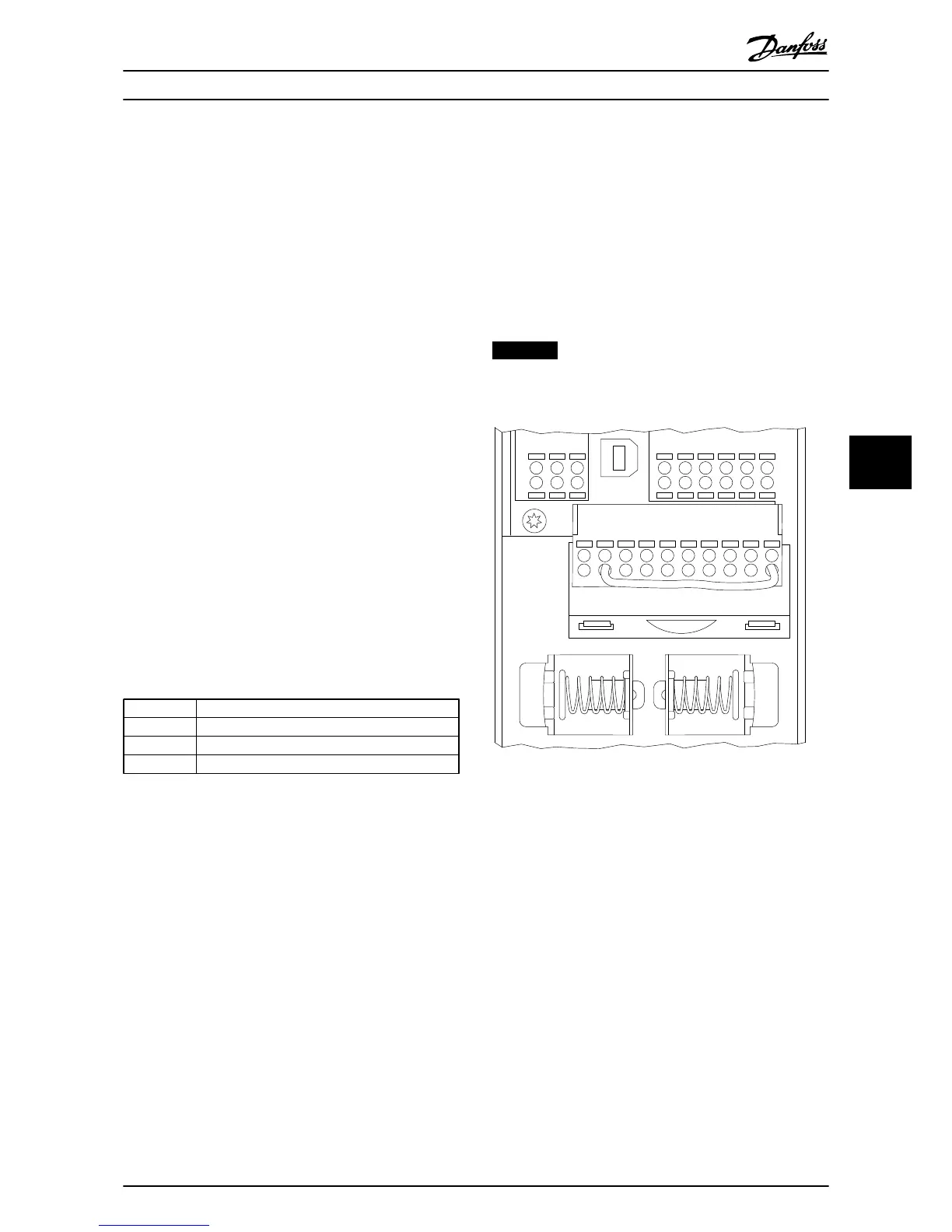
7.1.2
Network Connection
Connect the unit to the RS485 network as follows:
1. Connect signal wires to terminal 68 (P+) and
terminal 69 (N-) on the main control board of the
unit.
2. Connect the cable screen to the cable clamps.
NOTICE
Screened, twisted-pair cables are recommended to
reduce noise between conductors.