5 User Interface
5.1 Local Control Panel Operation
5.1.1 Modes of Operation
There are 2 ways to operate the unit:
•
Graphical Local Control Panel (GLCP)
•
RS485 serial communication or USB, both for PC
connection
5.1.2 How to Operate Graphical LCP (GLCP)
NOTICE
The active filter should be in Auto mode. Press [Auto On]
on the filter LCP.
Graphical display:
The LCD display is backlit with a total of 6 alpha-numeric
lines. All data is displayed on the LCP, which can show up
to 5 operating variables while in Status mode.
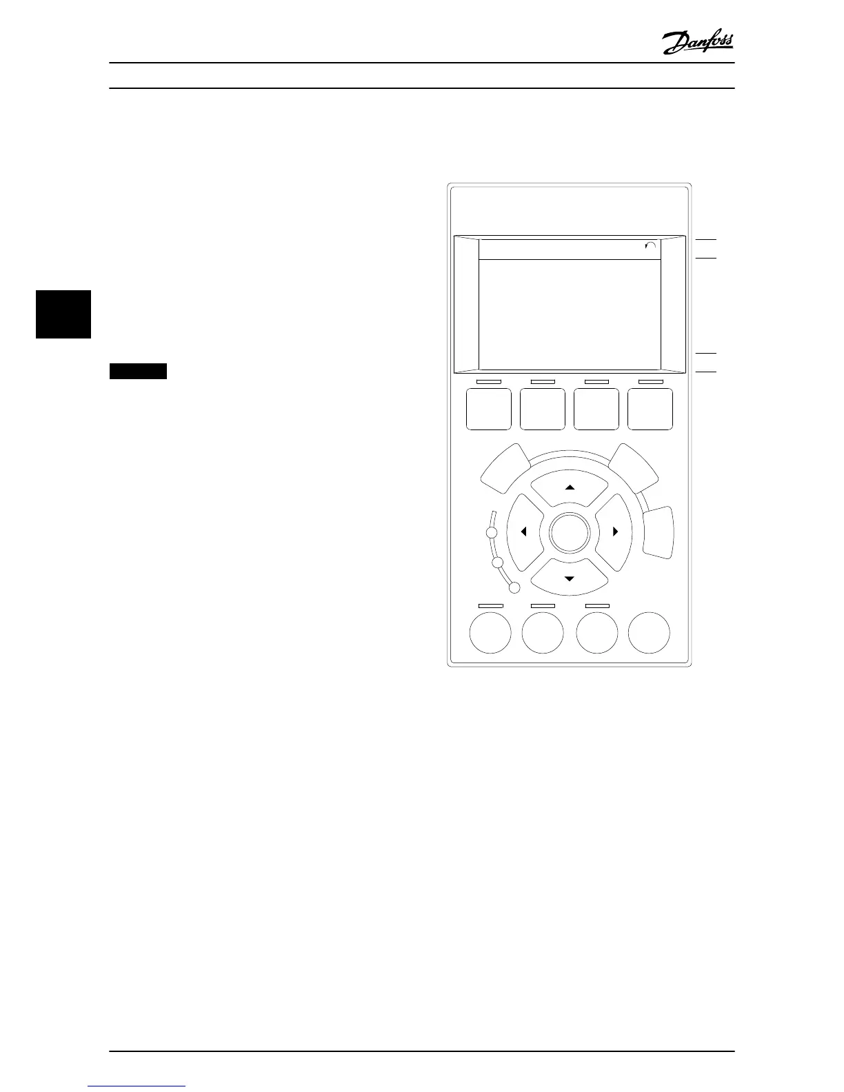
Illustration 5.1 shows an example of the frequency
converter LCP. The filter LCP looks identical but displays
information related to the filter operation.
1. Display:
1a
Status line: Status messages displaying
icons and graphics.
1b
Line 1–2: Operator data lines displaying
data and variables the user defines. Add
an extra line by pressing the [Status]
key.
1c
Status line: Status messages displaying
text.
2. Menu soft keys.
3. Indicator lights/navigation panel.
4. Operational keys.
Illustration 5.1 Example LCP
The display is divided into 3 sections:
Top section (a)
Shows the status when in status mode or up to 2 variables
when not in status mode and in the case of alarm/
warning.
The number of the active set-up (selected as the active
set-up in parameter 0-10 Active Set-up) is shown. When
programming in another set-up than the active set-up, the
number of the set-up being programmed appears to the
right in brackets.
Middle section (b)
Shows up to 5 variables with related unit, regardless of
status. In case of alarm/warning, the warning is shown
instead of the variables.
It is possible to toggle among 3 status readout displays by
pressing [Status].
User Interface
Operating Instructions
30 Danfoss A/S © 09/2014 All rights reserved. MG90V302
55