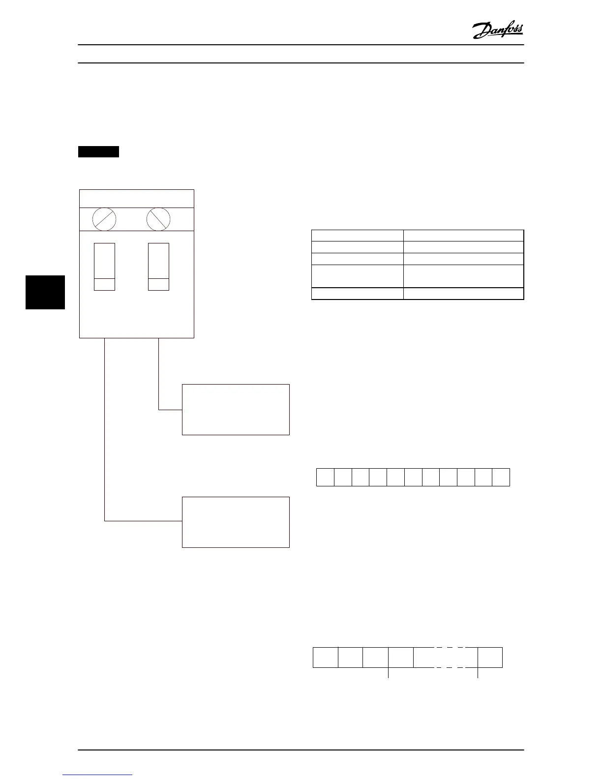
Illustration 7.2 Terminator Switch Factory Setting
7.1.4
EMC Precautions
The following EMC precautions are recommended in order
to achieve interference-free operation of the RS485
network.
•
Observe relevant national and local regulations
regarding protective ground connection.
•
Keep the RS485 communication cable away from
noisy cables such as power lines and motor
cables. Doing so reduces high frequency noise
transference. A distance of 200 mm (8 in) is the
minimum, but keeping the greatest possible
distance between cables is best, especially when
cables run in parallel over long distances.
•
When crossing cables is unavoidable, the RS485
cable must cross other power cables at a 90°
angle
7.2 Network Configuration
Set the parameters in Table 7.2 to enable the FC protocol
for the filter.
Parameter Number Setting
Parameter 8-30 Protocol
FC
8-31 Address
1-126
Parameter 8-32 FC Port
Baud Rate
2400-115200
8-33 Parity / Stop Bits
Even parity, 1 stop bit (default)
Table 7.2 Configuration Parameter Settings
7.3 FC Protocol Message Framing Structure
7.3.1 Content of a Character (byte)
Each character transferred begins with a start bit. Then 8
data bits are transferred, corresponding to a byte. Each
character is secured via a parity bit. This bit is set at 1
when it reaches parity. Parity is when there is an equal
number of 1s in the 8 data bits and the parity bit in total.
A stop bit completes a character, thus consisting of 11 bits
in all.
Illustration 7.3 Content of a Character
7.3.2 Telegram Structure
Each telegram begins with a start character (STX)=02 hex,
followed by a byte denoting the telegram length (LGE) and
a byte denoting the filter address (ADR). A number of data
bytes (variable, depending on the type of telegram)
follows. The telegram is completed by a data control byte
(BCC).