Total current [A] Maximum individual harmonic compensation
I5 I7 I11 I13 I17 I19 I23 I25
190 133 95 61 53 38 34 30 27
250 175 125 80 70 50 45 40 35
310 217 155 99 87 62 56 50 43
400 280 200 128 112 80 72 64 56
Table 4.10 Maximum Individual Harmonic Compensation
4.2.10 Operating with Capacitor Banks
The active filter is able to run with capacitor banks as long
as the resonance frequency of the capacitor bank is not in
the operation range of the active filter.
NOTICE
Always use de-tuned capacitor banks in installations with
frequency converters and active filters to avoid
resonance phenomena, unintended tripping or
component breakdown.
For de-tuned capacitors, the resonance frequency
capacitors should be tuned for an inter-harmonic number
lower than the 3rd harmonic.
NOTICE
If installed with capacitor banks of any kind, the active
filter must operate in selective compensation mode.
The capacitor bank should be installed upstream of the
filter toward the transformer. If this is not possible, install
the current transformers such that they do not measure
both needed current compensation and the capacitor
corrected current.
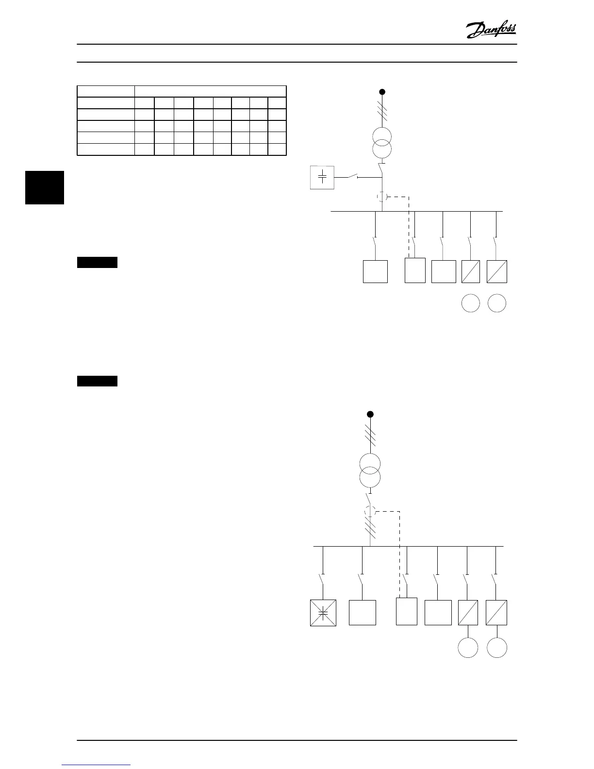
Illustration 4.13 Capacitor bank mounted upstream. CTs do
not measure capacitor current.
Illustration 4.13 shows recommended installation of the
active filter and CT placement in installations containing
capacitor banks.