Operating variables with different formatting are shown on
each status screen.
Several values or measurements can be linked to each of
the displayed operating variables. Define the values/
measurements to be displayed via parameters 0-20, 0-21,
0-22, 0-23, and 0-24.
Each value/measurement readout parameter selected in
parameters 0-20 to 0-24 has its own scale and number of
digits after a possible decimal point. Larger numeric values
are displayed with few digits after the decimal point.
Example: Current readout
5.25 A; 15.2 A 105 A.
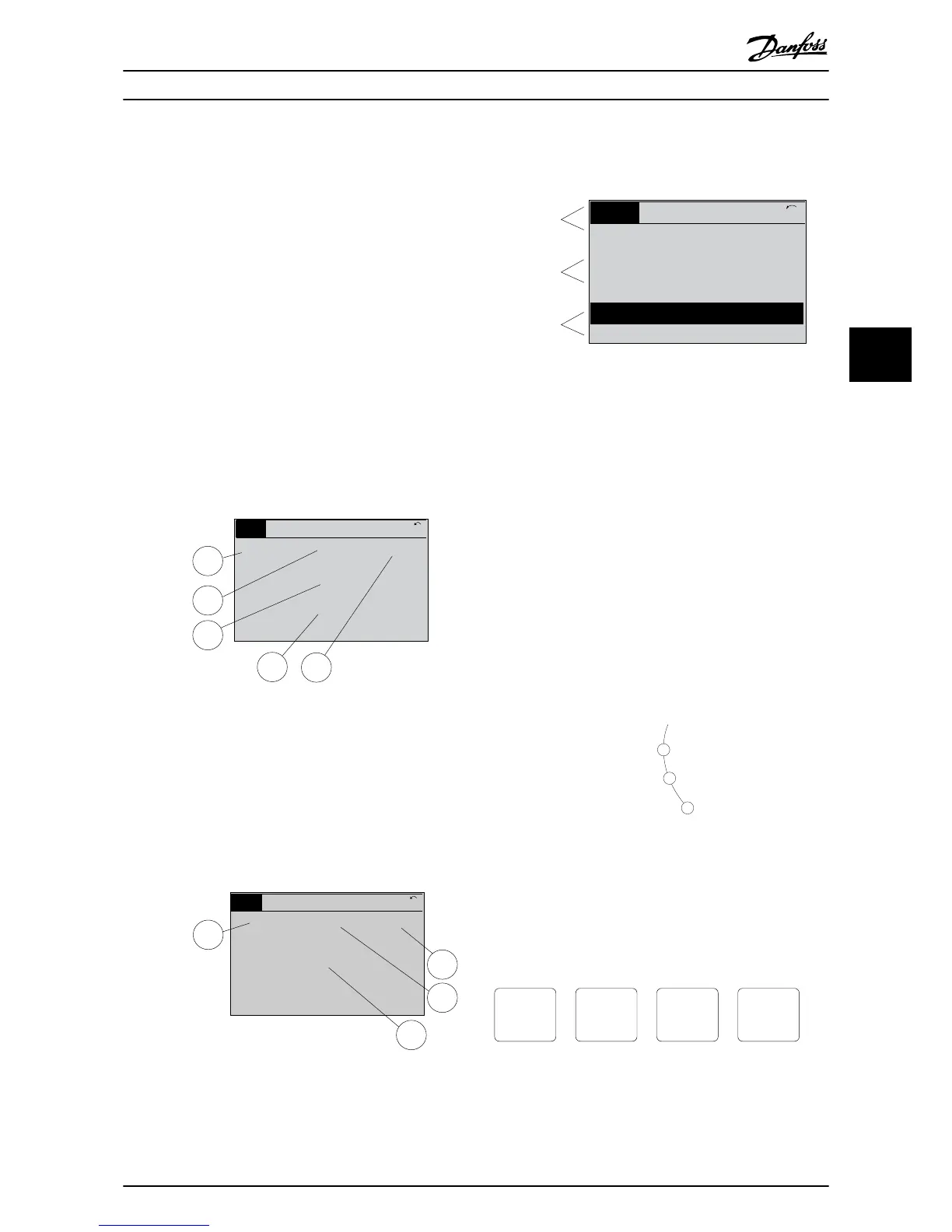
Status display I
This readout state is standard after start-up or initialisation.
Press [Info] to obtain information about the
value/ measurement linked to the displayed operating
variables (1.1, 1.2, 1.3, 2, and 3).
See the operating variables shown in the display in
Illustration 5.2. 1.1, 1.2 and 1.3 are shown in small size. 2
and 3 are shown in medium size.
1.1
2
3
1.3
1.2
130BP041.10
799 RPM
Auto Remote Ramping
1 (1)
36.4 kw7.83 A
0.000
53.2 %
Status
Illustration 5.2 Status Display I - Operating Variables
Status display II
See the operating variables (1.1, 1.2, 1.3, and 2) shown in
the display in Illustration 5.3.
In the example, speed, motor current, motor power, and
frequency are selected as variables in the first and second
lines.
1.1, 1.2 and 1.3 are shown in small size. 2 is shown in large
size.
1.1
1.2
2
1.3
130BP062.10
207RPM
Auto Remote Running
1 (1)
24.4 kW5.25A
6.9
Hz
Status
Illustration 5.3 Status Display II - Operating Variables
Bottom section
The bottom section always shows the state of the
frequency converter in Status mode.
Top section
Middle section
Bottom section
Status
43 RPM
1.4 Hz
Auto Remote Running
! Pwr.card temp (W29)
2.9%
5.44 A 25.3kW
1(1)
130BP074.10
!
Illustration 5.4 Bottom Section Status Mode
Display contrast adjustment
Press [status] and [
▲
] for darker display
Press [Status] and [
▼
] for brighter display
Indicator lights (LEDs):
If certain threshold values are exceeded, the alarm and/or
warning indicator lights are illuminated. A status and alarm
text appear on the control panel.
The On indicator light is activated when the active filter
receives power from:
•
Mains voltage.
•
A 24 V external supply.
Indicator lights (LEDs)
•
Green LED/On: Control section is working.
•
Yellow LED/Warn: Indicates a warning.
•
Flashing Red LED/Alarm: Indicates an alarm.
Illustration 5.5 LED Status Indicator Lights
LCP keys
Menu keys
The menu keys are divided into functions. The keys below
the display and indicator lights are used for parameter set-
up, including option of display indication during normal
operation.
130BP045.10
Status
Quick
Menu
Main
Menu
Alarm
Log
Illustration 5.6 Menu Keys
User Interface Operating Instructions
MG90V302 Danfoss A/S © 09/2014 All rights reserved. 31
5 5